
How the warning system gets attention
The flight deck combines colour, sound and tactile cues so urgency is recognisable before the crew reads the associated system light. The 737 uses master attention lights and system annunciators rather than a central message list.
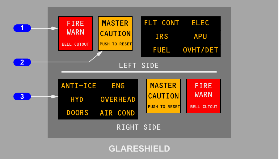
Colours and attention level
| Colour or cue | Meaning in this chapter | Typical example |
|---|---|---|
| Red | Requires immediate crew attention | Fire, unsafe gear, cabin altitude or takeoff configuration warning |
| Amber | Calls for timely awareness and corrective action | MASTER CAUTION and an associated system annunciator |
| Blue | Reports status, power availability, communication or valve position | A valve light bright during movement, then dim when positioned |
| Green | Confirms a commanded extended state | Landing gear or leading-edge device fully extended |
| Tactile or aural | Provides another channel when looking elsewhere | Stick shaker, clacker, bell, horn or voice callout |
Master fire warning
Either red FIRE WARN light comes on for a fire-warning input from an engine, the APU, the main wheel well or a cargo compartment. The fire bell accompanies the warning, and the remote APU horn also operates on the ground when applicable. Pressing either FIRE WARN light turns off both master lights, silences the associated bell or remote horn, and rearms the master circuit for another warning. The fire source indication remains the place to diagnose the event.
Master caution, reset and recall
An amber MASTER CAUTION light draws the eye to an amber condition outside the normal forward view. The related system annunciator names the group, such as FLT CONT, ELEC, HYD, OVERHEAD or AIR COND. Pressing either MASTER CAUTION clears both master lights and resets the attention system. Pressing a system annunciator panel recalls active cautions and stored single-channel faults. During press-to-test, all twelve annunciator legends should illuminate.
Configuration warnings and proximity logic
The takeoff and cabin-altitude warnings deliberately share an intermittent horn, so the illuminated red light identifies which condition exists. Landing-gear warning uses a steady horn and separate flap, thrust and radio-altitude logic.
Takeoff configuration
Ground logic arms the takeoff check as either forward thrust lever moves towards takeoff power. The intermittent horn and red TAKEOFF CONFIG light operate if any monitored item is outside its permitted departure state.
| Monitored item | Condition that produces the warning |
|---|---|
| Trailing-edge flaps | Outside the flap 1 through flap 25 takeoff range, or affected by skew, asymmetry or uncommanded travel |
| Leading-edge devices | Not in the takeoff state or moving without a command |
| Speedbrake system | Lever not DOWN, or the spoiler valve is supplying the ground-spoiler interlock |
| Parking brake | Set |
| Stabiliser | Trim outside the green takeoff range |
Cabin-altitude warning
At a cabin altitude above 10,000 feet, the same intermittent horn sounds and the red CABIN ALTITUDE light comes on. A momentary press of ALT HORN CUTOUT silences the horn, while the light stays on until cabin altitude falls enough for the pressure switch to reset. That reset occurs from 500 to 1,500 feet below the activation level.
Landing-gear warning
A steady horn indicates an approach to landing with a gear not down and locked. With flaps up through 10, the trigger depends on low radio altitude and thrust. Above 200 feet RA the HORN CUTOUT switch can silence this case; below 200 feet it cannot. With flaps 15 through 25 and low thrust, the horn is not cutout-resettable. Beyond flap 25, gear-up warning is independent of thrust and cannot be silenced. Correcting the configuration removes the warning.
PSEU monitoring
The proximity switch electronic unit watches takeoff and landing configuration logic, landing-gear position and air-ground sensing. In this configuration a single fault in certain duplicated channels produces the PSEU, OVERHEAD and MASTER CAUTION indications after landing. The PSEU light goes out when the parking brake is set or both engines are shut down. The light is suppressed in flight, during thrust advancement for takeoff, and for 30 seconds after touchdown.
Overspeed, stall and altitude alerting
Three separate protections cover maximum speed, approaching stall and deviation from the selected altitude. Each uses a different cue: clacker, control-column vibration, or a tone with display-box changes.
Mach and airspeed warning
Two independent channels monitor Vmo and Mmo. Passing the active maximum produces the unmistakable clacker. It cannot be cancelled by a switch; it stops only after airspeed returns below the applicable limit. Each warning channel has its own test switch, and testing is permitted only on the ground.
Stall warning
An eccentric motor on each control column creates the stick-shaker cue before the stall. Either shaker is felt through both columns because the columns are mechanically interconnected. The system is continuously armed in flight and disabled on the ground. Two independent SMYD computers determine the warning from angle-of-attack vane information, inertial data, anti-ice selection, wing configuration, air-ground state, thrust and FMC inputs.
With AC power available on the ground, STALL WARNING TEST No. 1 exercises the captain-side channel and No. 2 exercises the first-officer-side channel. Both columns vibrate during either successful test.
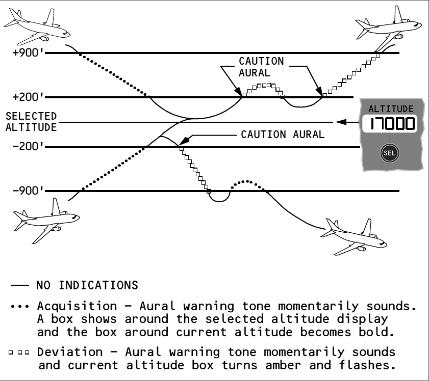
Altitude acquisition and deviation
As the aircraft closes to within 900 feet of the MCP-selected altitude, a momentary tone sounds, a white outline appears around the selected value, and the current-altitude box becomes bold. For this configuration the acquisition boxes disappear at 200 feet from the target. After capture, a 200-foot departure produces another tone and makes the current-altitude box flash amber. Flashing ends when the error falls below 200 feet, grows beyond 900 feet, or a different altitude is selected.
Altitude alerting is inhibited with trailing-edge flaps at 25 or more, and while glideslope is captured.
Radio-altitude ground proximity protection
Basic GPWS combines radio altitude with barometric altitude, speed, landing configuration and approach-path deviation. It recognises hazardous trends near the ground, but it is not a terrain-clearance guarantee.
What basic GPWS monitors
| Hazard | Principal aural cue | Meaning |
|---|---|---|
| Excessive descent rate | SINK RATE, then PULL UP | The descent rate is unsafe for the measured height |
| Rapid terrain closure | TERRAIN, then PULL UP | Terrain separation is reducing too quickly |
| Height loss after takeoff or go-around | DON'T SINK | The aircraft is losing altitude during an initial climb segment |
| Unsafe landing configuration | TOO LOW FLAPS or TOO LOW GEAR | Height and speed are incompatible with flap or gear position |
| Unsafe clearance at higher speed | TOO LOW TERRAIN | Gear or flap state is unsuitable for the current terrain clearance |
| Low approach path | GLIDESLOPE | Deviation below ILS, GLS or the generated flight-path angle is excessive |
Controls and inhibits
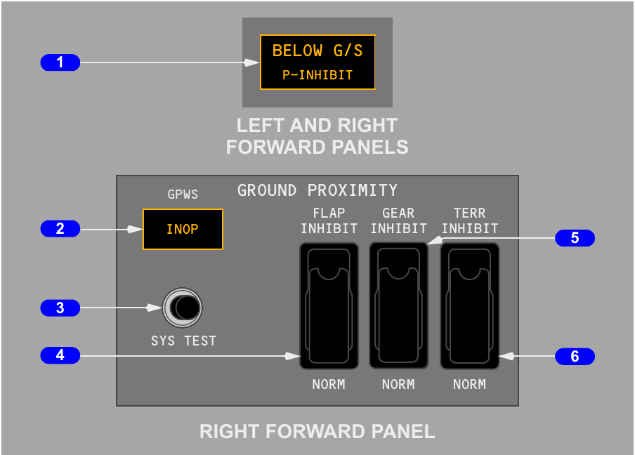
BELOW G/S glows amber during the low-glideslope alert. Below 1,000 feet RA, pressing it cancels or inhibits that alert. FLAP INHIBIT removes TOO LOW FLAPS, GEAR INHIBIT removes TOO LOW GEAR, and TERR INHIBIT removes the look-ahead terrain display and alerts. The guarded NORM position restores each function.
GPWS INOP indicates loss of the computer, power, or a required input. A ground-only SYS TEST checks the lamps, display patterns and aural channels. The basic modes have important blind areas: they may not warn of a near-vertical terrain face or a gradual descent into unprepared terrain while the aircraft is already in a landing configuration.
Look-ahead terrain and obstacle alerts
Enhanced GPWS adds a worldwide terrain database and GPS-referenced look-ahead logic. It projects the aircraft path into the database and ranks the alert by estimated time remaining before impact.
Terrain presentation
Terrain within 2,000 feet of aircraft barometric altitude can appear on the navigation display. Airport regions contain greater database detail than remote areas. Position comes from GPS, while alert prediction also considers barometric altitude, vertical flight path and groundspeed. This presentation supports situational awareness; it is not an independent means of navigation.
Terrain and weather radar cannot occupy the same display continuously. If one pilot selects terrain while the other selects weather, the displays update on alternating antenna sweeps. Route and traffic information may remain overlaid with terrain.
Caution and warning levels
| Level | Typical time to projected impact | Display and aural result |
|---|---|---|
| Caution | About 40 to 60 seconds | Amber terrain or obstacle area with CAUTION TERRAIN or CAUTION OBSTACLE |
| Warning | About 20 to 30 seconds | Solid red threat, PULL UP on both attitude displays, plus TERRAIN or OBSTACLE and PULL UP voice warning |
For this configuration, the obstacle function also considers man-made objects at least 100 feet high. TERR INHIBIT suppresses both terrain and obstacle look-ahead functions. An actual windshear warning takes priority and suppresses radio-altitude and look-ahead ground-proximity alerts.
Windshear protection and approach callouts
Two systems address windshear. GPWS detects an encounter at the aircraft, while the weather radar searches ahead for disturbed air that contains enough moisture or particles to produce a radar return.
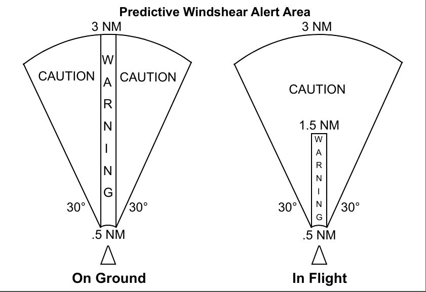
Reactive warning
GPWS encounter logic starts at rotation and is enabled below 1,500 feet RA. Excessive windshear at the aircraft produces a two-tone siren, repeated WINDSHEAR voice calls and red WINDSHEAR messages on both primary flight displays.
Predictive warning and caution
The radar begins automatic windshear scanning when thrust is set for departure or when airborne below 2,300 feet RA. Its predictive alerting envelope extends below 1,200 feet RA, and indications become available about 12 seconds after scanning starts. A caution ahead within 3 NM gives an amber WINDSHEAR indication and MONITOR RADAR DISPLAY. A close threat gives a red warning with WINDSHEAR AHEAD on takeoff or GO AROUND, WINDSHEAR AHEAD on approach.
During takeoff or landing, new predictive cautions are inhibited from 80 knots to 400 feet RA. New predictive warnings are inhibited from 100 knots to 50 feet RA. An alert already active before entering an inhibit band remains displayed and completes its aural message. Radar prediction cannot detect every type of shear, especially where there is too little moisture or particulate content.
Approach callouts for this configuration
The installed radio-altitude sequence is FIVE HUNDRED using Smart 500, then ONE HUNDRED, FIFTY, TWENTY and TEN. The minima cue is MINIMUMS at the captain's selected DH or MDA. RADIO minimums use radio altitude; BARO minimums use barometric altitude.
Smart 500 calls FIVE HUNDRED on a non-ILS or non-GLS approach. It also treats backcourse, glideslope cancel, or a path more than two dots from valid localiser or glideslope guidance as a non-precision situation for this purpose.
TCAS traffic and resolution advisories
TCAS interrogates nearby operating transponders, predicts relative paths, and warns when closure creates a collision risk. It functions independently of ground-based air traffic control, but it cannot provide traffic guidance for an aircraft whose transponder is not replying.
TA and RA sequence
A traffic advisory is normally generated about 40 seconds before closest approach. If closure continues, a resolution advisory follows at roughly 25 seconds and supplies both voice guidance and a commanded vertical manoeuvre. An RA requires reported altitude from the threat aircraft; without it, TCAS may still show traffic but cannot create vertical resolution guidance.
| Traffic class | Indication | Crew meaning |
|---|---|---|
| Other | Open white diamond | Outside the proximate criteria |
| Proximate | Filled white diamond | Within 6 NM and 1,200 feet vertically, without a predicted TA or RA |
| TA | Amber circle and TRAFFIC, TRAFFIC | Prepare to acquire the traffic and for a possible RA |
| RA | Red square with aural vertical guidance | Fly the commanded pitch response unless a higher-priority warning intervenes |
When available, the symbol includes relative altitude and an arrow for vertical movement exceeding 500 feet per minute. A threat without bearing is presented in a text block containing range, altitude and vertical trend. OFFSCALE appears when the selected display range cannot place a TA or RA symbol on the map. If neither pilot has traffic selected, a TA or RA can automatically bring up traffic in a supported navigation-display mode.
Mode and inhibit logic
TA ONLY shows traffic advisories without resolution commands. TA/RA enables both. During descent, INCREASE DESCENT RAs are removed below approximately 1,500 feet RA, DESCEND RAs below 1,100 feet RA, and all RAs below 1,000 feet RA. Below that point the equipment automatically behaves as TA ONLY. TCAS voice is inhibited below about 500 feet RA, and any GPWS or windshear warning suppresses all TCAS alerts.
Resolution language
MONITOR VERTICAL SPEED keeps pitch away from the prohibited band. CLIMB or DESCEND commands the displayed pitch, LEVEL OFF requests zero vertical speed, and an INCREASE command strengthens the initial response. A reversal such as CLIMB, CLIMB NOW replaces the original opposite-direction RA.