
FMS architecture and the flight sequence
The flight management system joins navigation, performance calculation, flight planning and guidance. The FMC is the computing core, the CDUs are the crew interface, and the automatic flight system follows the commands only after the crew has selected or accepted the appropriate mode.
Two computers, one active solution
Two flight management computers normally operate together. One is primary and the other follows it. The primary FMC manages functions such as radio tuning, builds guidance commands and synchronises common route and performance data with the other unit. Each CDU remains a separate interface, so a display or keyboard problem is not automatically an FMC failure.
| Layer | Purpose | Crew check |
|---|---|---|
| Navigation | Combines position sources and follows the active route | Route, active leg, position agreement, ANP and RNP |
| Performance | Predicts speeds, altitude capability, time and fuel | Gross weight, fuel, cost index, cruise altitude and winds |
| Guidance | Supplies lateral and vertical commands | FMA, MCP selections and aircraft response |
Normal and single FMC operation
The FMC source selector is normally left in NORMAL. A BOTH ON L or BOTH ON R selection makes one computer drive both sides. That is a deliberate reversion and is used only when the applicable procedure calls for it. The selected source must agree with the CDU and display information being trusted.
Flight phases
The system changes its calculations as the flight moves through preflight, takeoff, climb, cruise, descent, approach and go around. The phase controls which performance pages, limits and predictions are relevant. Phase changes do not remove the need to verify route continuity, active modes and altitude clearances.
The CDU: pages, prompts and execution
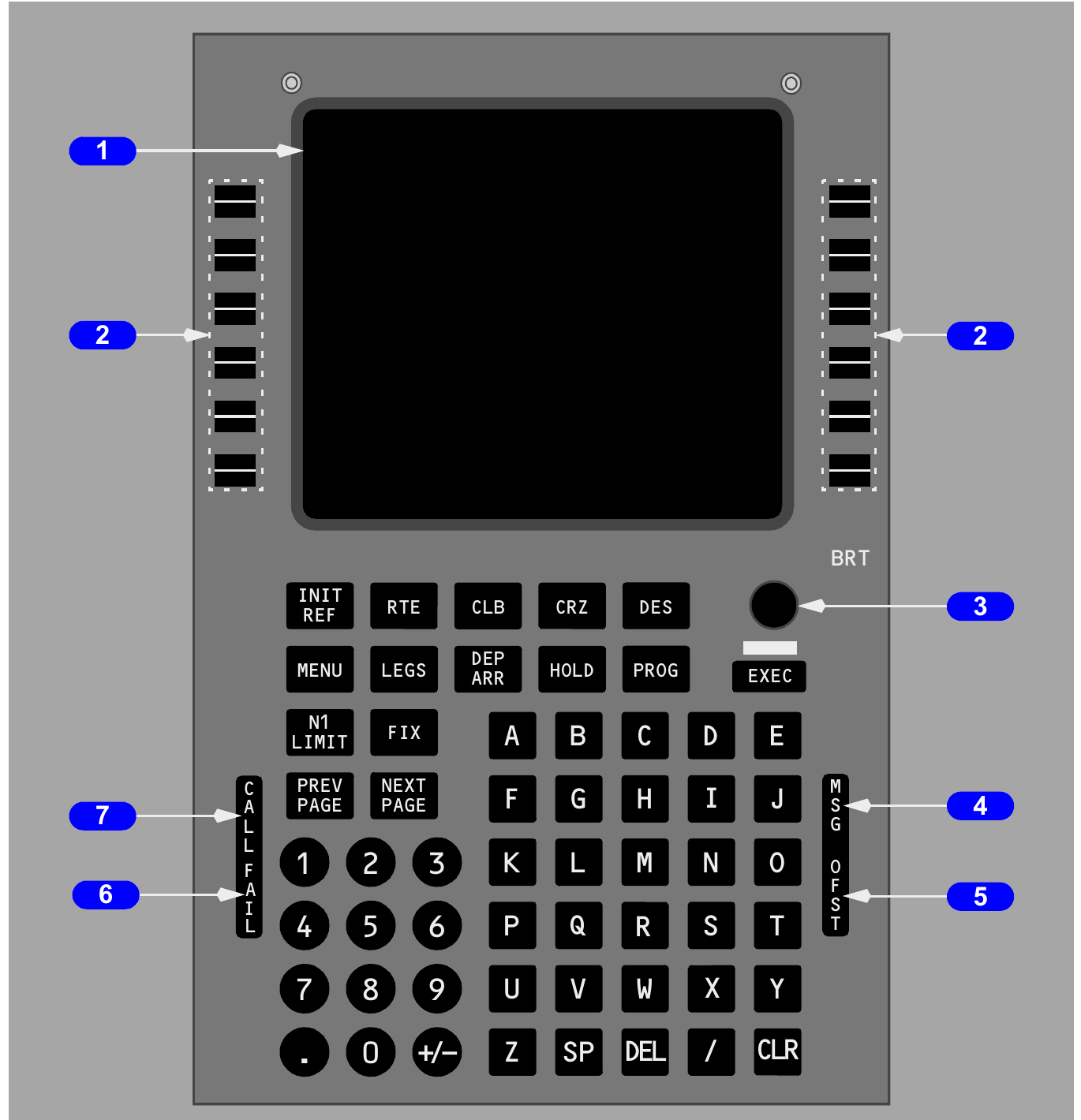
The CDU is where the crew enters and reviews FMC data. Understanding line-select keys, the scratchpad, page prompts and the EXEC light prevents an entry error from becoming an active route or performance change.
Display fields and line-select keys
Data beside a line-select key can be selected, copied or replaced. A boxed field requires an entry. Dashes invite optional data. Small-font values are generally computed or predicted, while large-font entries normally represent crew-entered or active data. A page prompt leads to another related page.
The scratchpad
Keyboard entries first appear in the scratchpad. Selecting a line-select key moves the scratchpad entry to the associated field. Selecting a displayed value can copy it to the scratchpad. CLR deletes characters or clears a message, while DEL allows a permitted field to be removed. A scratchpad message must be understood before it is cleared.
Modified and active data
An entry that changes the route or a performance solution normally creates a modification. The change remains pending until EXEC is selected. The illuminated EXEC key is therefore a warning that the displayed modification has not yet become active. ERASE removes a pending modification and restores the active data.
- Enter the value in the scratchpad.
- Place it in the intended field.
- Review the complete effect, especially discontinuities and constraints.
- Select EXEC only when the modification is correct and cleared.
- Confirm the expected FMA and aircraft response.
Preflight initialisation and route activation
A complete preflight gives the FMC a valid starting position, a continuous route and enough aircraft data to calculate takeoff and climb guidance. Missing or inconsistent data must be resolved before relying on predictions.
Required preflight groups
| Group | Typical entries | Reason |
|---|---|---|
| Position | Reference airport or gate and present position | Initialises the inertial and navigation solution |
| Route | Origin, destination, runway, route legs and procedure | Creates the lateral flight plan |
| Performance | Reserves, cost index, cruise altitude and transition altitude | Builds speed, time, altitude and fuel predictions |
| Takeoff | Flap, centre of gravity, V speeds and thrust selection | Provides takeoff reference data |
Optional entries can include a navigation database selection, a second route, departure and arrival procedures, an RTA, forecast wind and a reduced thrust method. Optional does not mean unimportant. Use each item when it materially improves the planned operation.
Build and inspect the route
Enter the route from the clearance rather than from expectation. Review every airway, waypoint, direct segment, procedure and runway. A route discontinuity is a deliberate break in the path. Remove it only when the intended connection is known and the clearance permits the connection.
Activation prepares the route for execution. Execution makes it active. Review the LEGS pages and the ND before takeoff, looking for incorrect waypoint order, unexpected turns, duplicate fixes, route gaps and unreasonable leg distances.
Performance consistency
Gross weight, zero fuel weight and fuel entries must be mutually reasonable. Cruise altitude must be compatible with the route, aircraft capability and clearance. Incorrect data can produce plausible looking but unsafe speed, thrust and fuel predictions.
Inertial reference alignment and power
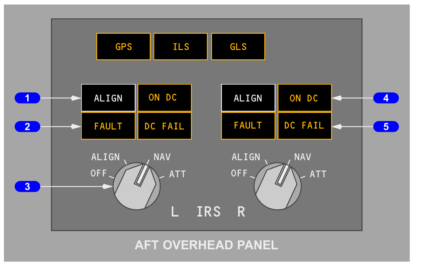
The two inertial reference systems provide attitude, heading, acceleration, track and inertial position data. A correct alignment begins with a stationary aircraft, reliable present position and the selectors placed in NAV.
Normal alignment
Moving a selector from OFF to NAV begins alignment when the aircraft is within the permitted latitude range, 78 degrees 15 minutes north to 78 degrees 15 minutes south. Alignment time varies with latitude and is normally about 5 to 17 minutes. The system uses stored magnetic variation over most operating latitudes.
The entered position must be within 4 NM of the origin airport position or the VERIFY POSITION message appears. The aircraft must remain stationary. Movement during alignment causes the system to require a new full alignment.
Fast realignment and ATT mode
A fast realignment takes about 30 seconds and refreshes attitude and heading while retaining present position. It is useful only when the required conditions are satisfied. If alignment is lost in flight, ATT mode can restore attitude after about 30 seconds of straight, level and unaccelerated flight. Heading then requires manual entry and can drift by as much as 15 degrees per hour.
Power and shutdown
The left and right systems normally use separate AC sources and have hot-battery backup. The right system's backup DC supply is limited to about five minutes if normal AC is not restored. After a selector is moved to OFF, the system remains powered for about 30 seconds to complete shutdown, with ALIGN illuminated during that period.
Radio navigation and station identification
Radio aids support raw-data navigation, approach guidance and FMC position updating. Automatic tuning reduces workload, but it does not remove the requirement to confirm the selected aid and its identification.
VOR and DME use
VOR frequencies can be selected manually for bearing information. The FMC can automatically tune DME stations for position updating, including stations whose associated VOR is not being displayed. A DME identity may therefore be received without a collocated VOR indication.
ILS selection
The ILS frequency is manually tuned for an ILS approach. A decoded identifier can appear on the display, but the system does not prove that identifier against the navigation database. If a frequency remains selected or the displayed identity is doubtful, verify the Morse identifier and compare the front course with the published procedure.
| Source | Main use | Cross-check |
|---|---|---|
| VOR | Magnetic bearing or course | Frequency, identifier and expected bearing |
| DME | Slant range and FMC position updating | Identifier and plausible distance |
| ILS | Localiser and glide path guidance | Frequency, Morse identity and inbound course |
Raw data and managed position
An FMC map is a computed presentation. Raw radio bearings and distances provide an independent reasonableness check. During approach, compare the displayed course, distance and deviation with the chart and the aircraft's actual position.
Weather radar and predictive windshear
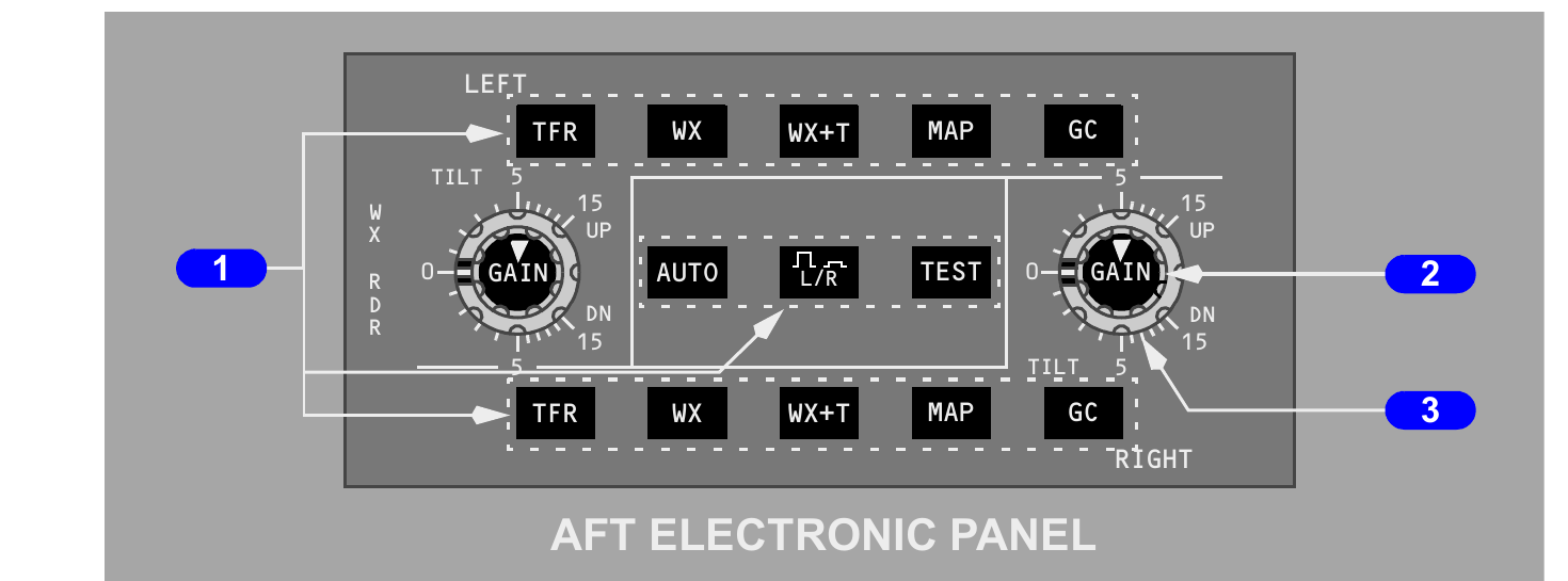
The installed weather radar provides automatic scanning, precipitation returns, turbulence information and predictive windshear alerts. It is an avoidance tool, not a device for finding a safe path through a severe cell.
Returns and turbulence
Increasing precipitation intensity is shown by changing colours, with red representing the strongest normal return. Magenta can identify turbulence within strong moisture returns. Turbulence detection is limited to approximately 40 NM because reliable velocity information requires a sufficiently strong return.
Automatic protection
The system normally scans a broad sector ahead. Path attenuation correction warns when intervening precipitation may be hiding weather beyond it. In automatic or calibrated-gain operation, that protection can assess thunderstorms within approximately 80 NM. Above 22,000 feet, overflight protection uses lower-beam information to reveal cells that might otherwise sit below the displayed flight-level slice, especially within about 15 NM.
Predictive windshear
Near the ground, the radar scans ahead for windshear. A warning region is closest to the projected path; caution information covers a wider region. Availability and alert type change with height and flight phase. During descent, both caution and warning alerts are available from about 1,200 to 400 feet, warnings remain available down to about 50 feet, and new alerts are inhibited below that point.
Predictive windshear is forward looking. The reactive windshear system responds to the aircraft's measured energy state. One system does not replace the other.
FMC position, ANP and RNP
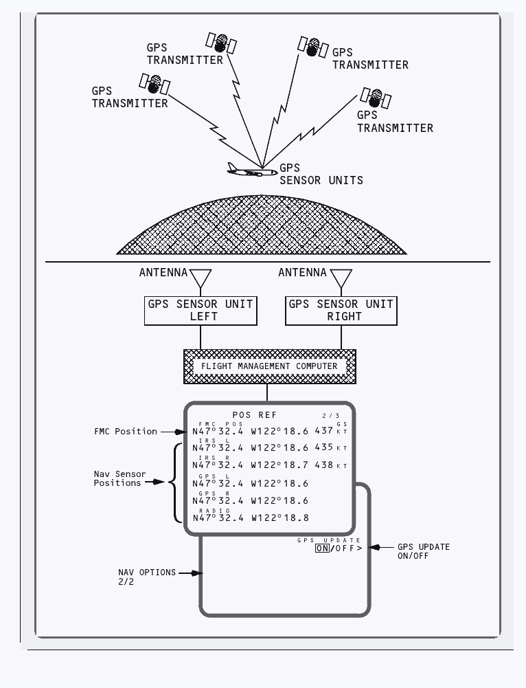
The FMC builds one navigation position from the best available sensors. The crew judges whether that solution is suitable by comparing actual navigation performance with the required performance for the operation.
Position sources and blending
The system can use GPS, inertial and radio-derived positions. On the ground, GPS normally provides the current FMC position when available; inertial position can support it when GPS is absent. In flight, source comparison and blending produce the FMC position while isolating unsuitable updates.
Actual and required performance
ANP expresses the computer's 95 percent estimate of present horizontal position uncertainty. A smaller ANP means the system estimates better accuracy. RNP is the maximum navigation error permitted for the current airspace or procedure. The basic relationship is simple: ANP must remain equal to or smaller than RNP.
| Comparison | Meaning | Crew response |
|---|---|---|
| ANP less than RNP | Estimated accuracy meets the requirement | Continue normal monitoring |
| ANP approaching RNP | Margin is reducing | Check sensor status and operational requirements |
| ANP greater than RNP | Required performance is not met | Respond to the navigation-performance alert and use an allowed alternative |
The message UNABLE REQD NAV PERF-RNP indicates that the required horizontal performance cannot be assured. It is an operational limitation, not merely an advisory message.
LNAV and lateral route management
LNAV uses the active FMC route to command lateral guidance. Safe use depends on a continuous route, the correct active leg and geometry that the automatic flight system can capture.
Engagement geometry
When the aircraft is within 3 NM of the active route leg and its intercept angle is no more than 90 degrees, selecting LNAV can engage it. If the geometry is not suitable, LNAV normally arms and waits for an intercept. The FMA is the final confirmation of engagement.
Leg sequencing
The active leg runs from the previous waypoint to the active waypoint. As the aircraft approaches a fly-by waypoint, the FMC anticipates the turn to join the next leg. Some procedure legs are defined by heading, track, altitude or intercept rather than by a simple straight line between two fixes.
Direct-to and intercept changes
Selecting a waypoint to the top of the LEGS page creates a proposed direct path. Before execution, compare it with the clearance and inspect the ND for the turn direction, intervening terrain or airspace, and the removal of any required waypoint. A modified leg must not be executed merely to tidy the route display.
| Situation | Review before EXEC |
|---|---|
| Direct to a waypoint | Turn direction, track, distance and omitted fixes |
| Route discontinuity | Whether a connection is intended and cleared |
| Procedure change | Runway, transition, constraints and route continuity |
| Vector to intercept | Heading, capture geometry and active leg |
VNAV constraints and path logic
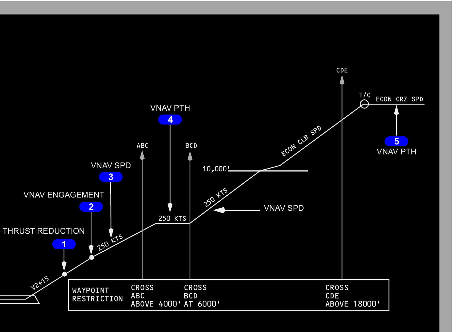
VNAV calculates a vertical profile from aircraft data, performance entries, route constraints and forecast conditions. It commands pitch and thrust through the automatic flight system, but it cannot override the altitude selected on the MCP.
Constraint notation
A waypoint can carry a speed restriction, an altitude at, an altitude at or above, an altitude at or below, or a window between two altitudes. On the LEGS page, the order and symbols show exactly which limit applies. A crew entry must retain any published or cleared restriction unless ATC has cancelled it.
Command roles
During climb, VNAV selects suitable target speeds and thrust references while respecting the route and MCP altitude. In cruise it maintains the planned cruise condition and updates predictions. During a path descent, pitch normally controls the vertical path while thrust is reduced or adjusted to control speed.
Path versus speed
Wind error, an early descent, speedbrake use or an unexpected restriction can move the aircraft above or below the computed path. Corrective action depends on the FMA, vertical deviation, speed trend and remaining distance. A speed intervention feature described for some variants is not installed in this configuration, so mode selections must follow the controls actually fitted.
Climb, cruise, step climb and RTA
The FMC changes its target to suit climb and cruise while continuously recalculating altitude capability, fuel and time. These predictions depend on accurate weight, temperature and wind information.
Climb scheduling
VNAV normally observes the departure speed restrictions and entered waypoint constraints, then accelerates to the climb schedule when altitude and configuration permit. A climb speed or altitude constraint is part of the active vertical plan and must be checked against the clearance.
Cruise and cost index
The cruise page shows planned cruise altitude, target speed and predictions. Cost index balances time cost against fuel cost. A cost index of zero produces a maximum-range objective. Increasing the value gives greater weight to time, and the valid range extends to 500, which represents the minimum-time end of the schedule.
Step climb
As weight reduces, the optimum and maximum altitudes can rise. A step altitude lets the FMC calculate the distance, time and fuel effect of a higher level. The maximum-altitude calculation includes current performance margins, while the step prediction uses forecast and actual wind information where applicable. The displayed step is planning data until the climb is cleared and the MCP is set.
Required time of arrival
An RTA associates a required crossing time with a route waypoint. The FMC can adjust the speed schedule within available limits to meet it. If the required time is outside the achievable range, the prediction or message indicates that the target cannot be met.
Descent planning and vertical-path control
A managed descent is built backwards from the end-of-descent point through altitude and speed constraints. The FMC predicts the top of descent, but the crew must still obtain clearance and select an MCP altitude that allows descent.
Top and end of descent
The top-of-descent point represents the calculated start of an idle or near-idle path to meet the planned lower constraints. The end-of-descent point connects the descent to the approach or terminal profile. Changes in wind, speed, anti-ice use, routing or restriction can move both points.
Starting early
If descent is initiated before the computed path, the system commands a shallow descent of about 1,000 feet per minute until the idle path is intercepted. The aircraft then transitions to path control. The crew should monitor altitude capture, vertical deviation and energy rather than waiting for an FMC message to reveal a problem.
Energy management
| Condition | Likely indication | Response concept |
|---|---|---|
| Above path | Excess height or energy | Use the approved speed, drag or path correction while protecting limits |
| Below path | Insufficient height or energy | Reduce descent or add thrust as appropriate |
| Speed increasing | Idle path cannot hold both speed and path | Control speed and reassess the vertical plan |
| New restriction | Profile recalculates | Verify the new constraint and route geometry before EXEC |
In a normal path descent, pitch controls the path and thrust is used to manage speed. If speed exceeds the target by more than about 15 knots in a path descent, protection logic can disconnect the automatic throttle and alert the crew to intervene.
IAN and approach guidance
Integrated approach navigation can present non-ILS approach guidance with familiar localiser-like and glide-path-like cues. The source, mode annunciation and approach minima still define what the guidance means.
FAC and G/P
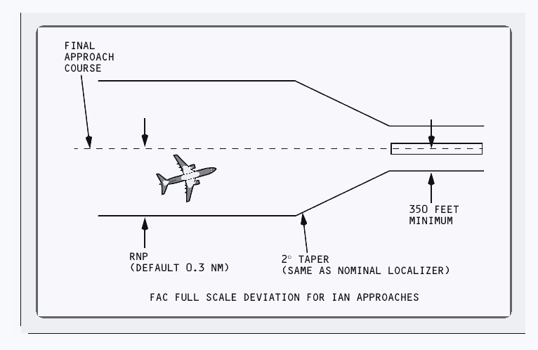
FAC is the lateral approach-guidance mode and G/P is the vertical path mode. They are FMC-generated guidance, even though the presentation resembles localiser and glide-slope cues. Arm and capture status must be confirmed on the FMA.
Scaling and procedure limits
The depicted installation uses a default lateral RNP of 0.3 NM for IAN approach scaling. Full-scale lateral deviation tapers towards the final course at two degrees and is limited to a minimum width equivalent to 350 feet near the runway. These values describe the fitted configuration and do not change the published minima.
Approach type, database coding, navigation performance and crew qualification all remain relevant. If actual performance no longer meets the required value, the approach cannot be continued merely because the deviation pointer looks centred.
Go-around and missed-approach logic
During a go around, automatic-flight and FMC logic must transition from approach guidance to missed-approach guidance. The crew follows the procedure while confirming thrust, pitch, lateral mode and altitude control.
Transition to go-around
When go-around conditions are met below approximately 2,000 feet radio altitude, selecting the takeoff or go-around switch commands go-around guidance. The exact automatic-flight response depends on system status and engagement. The FMA must be read immediately, followed by the flight-path response.
Lateral navigation after liftoff
LNAV can engage above 400 feet radio altitude when the active missed-approach path and engagement conditions are satisfied. Until it engages, fly the commanded or required lateral mode. Never turn towards a magenta missed-approach route before confirming that the clearance and active leg agree.
Vertical and route checks
- Apply and verify go-around thrust and pitch guidance.
- Confirm a positive climb and complete the required configuration changes.
- Set or verify the cleared missed-approach altitude on the MCP.
- Confirm the missed-approach route is active and free of an unintended discontinuity.
- Read the FMA after every mode change.
The FMC route may contain the published missed approach, but ATC can issue different instructions. The clearance takes precedence and must be entered or flown using an appropriate mode.
Performance data and thrust management
The FMC calculates thrust references and performance predictions from aircraft weight, environmental data and crew selections. Every reduced-thrust method preserves a defined relationship with the aircraft's certified limits.
Navigation database currency
The FMC holds two navigation database sets, each valid for 28 days. Select and verify the set whose active dates cover the operation. Database currency does not guarantee that every route or procedure entry is correct, so chart comparison remains essential.
Thrust references
Available references include takeoff, derated takeoff, assumed-temperature takeoff, climb, reduced climb, cruise, maximum continuous and go-around thrust. The selected reference supplies an N1 target appropriate to the phase and entered conditions.
| Method | Purpose | Important boundary |
|---|---|---|
| Fixed derate | Uses a lower certified thrust rating | Performance must be calculated for that rating |
| Assumed temperature | Commands less takeoff thrust by entering a higher assumed temperature | Maximum reduction is 25 percent |
| CLB-1 | Reduces climb N1 by about 3 percent | Thrust returns gradually towards full climb |
| CLB-2 | Reduces climb N1 by about 6 percent | Thrust returns gradually towards full climb |
Reduced climb selections progressively restore full climb thrust and are automatically deleted above 15,000 feet. The takeoff thrust-reduction height can be entered between 800 and 9,999 feet where the approved procedure permits.
When VNAV is active, automatic-throttle wake-up can restore speed protection when actual speed falls about 5 knots below the command speed. It is a protection layer, not a substitute for speed monitoring.
Fuel predictions, cost and FMC power interruptions
FMC fuel predictions are only as reliable as the sensed quantity, route and performance model. Messages identify disagreement or reserve risk, while power-interruption logic determines what must be recovered.
Fuel quantity and prediction messages
| Message | Meaning | Required thought |
|---|---|---|
| VERIFY GW AND FUEL | Automatic weight or fuel data is unavailable or inconsistent | Enter and periodically update valid manual values |
| CHECK FMC FUEL QUANTITY | An unexpected decrease has been detected | Compare FMC and aircraft indications and investigate the cause |
| USING RSV FUEL | Predicted arrival fuel is below the entered reserve | Reassess route, weather and diversion options |
| INSUFFICIENT FUEL | Predicted destination fuel is 2,000 pounds or less | Take prompt operational action |
When fuel must be entered manually, update the estimate approximately every 30 minutes. The manual estimate is not normally updated during descent when approach reference speed is being used. Always compare the predicted landing fuel with the independent fuel-quantity indication.
Cost index effect
Cost index changes the time and fuel trade. Zero favours maximum range. Higher values progressively favour time, up to the valid maximum of 500. It does not override structural, placard or operating speed limits.
Power interruption recovery
An interruption shorter than 10 seconds normally allows the FMC to retain data and resume. After a longer interruption on the ground, repeat the full preflight. In flight, retained data may allow recovery, but the crew must review the route legs, select the correct active waypoint or leg and verify every restored entry.
Messages, monitoring and recovery
FMC messages point to missing data, a changed condition or an operation the system cannot complete. The correct response is to identify the affected layer, repair the cause and verify the result.
Message priorities
A CDU scratchpad message is cleared only after it is read and understood. Some messages request an entry, some report degraded navigation or performance, and others warn that the active profile can no longer meet a requirement. Clearing the text does not clear the condition.
| Message or cue | What it points to | Useful first check |
|---|---|---|
| UNABLE REQD NAV PERF-RNP | ANP exceeds the required horizontal performance | Sensor status, RNP value and permitted alternative |
| RESET MCP ALT | The selected altitude prevents the planned vertical change near top of descent | ATC clearance and MCP altitude |
| VERIFY POSITION | The entered position is inconsistent during alignment | Gate or airport position and entry accuracy |
| EXEC light | A route or performance modification is pending | Modified page, route geometry and clearance |
A disciplined recovery sequence
- Keep the aircraft on a safe flight path using reliable basic modes or manual control.
- Read the FMA and identify the active guidance.
- Read the message without immediately clearing it.
- Check the relevant source, entry, route leg or performance limit.
- Correct one layer at a time and review the resulting modification.
- Confirm the map, raw data, MCP and aircraft response agree.
What the chapter connects
The inertial and radio systems provide navigation inputs. The FMC turns those inputs and the active database into a route, position and performance plan. LNAV and VNAV create guidance. The automatic flight system follows that guidance only through active modes, while displays and messages let the crew monitor the chain.