
System architecture and mode awareness
The automatic flight system combines the autopilot flight director system with the autothrottle. Crews command it through one mode control panel and verify every response on the flight mode annunciation.
AFS, AFDS and FCCs
The automatic flight system, or AFS, includes the autopilot flight director system, called AFDS, and the autothrottle. Two flight control computers, FCC A and FCC B, process guidance. Either FCC can command a flight director and an autopilot. A single mode control panel, or MCP, supplies selected speed, heading, altitude and vertical-speed targets to both sides.
The flight directors can operate with or without the autopilot or autothrottle. Their command bars show the attitude needed to follow the active roll and pitch modes. During an ILS approach, the bars retract from view near 50 feet radio altitude because the flight directors do not provide a flare command.
Read the FMA before the control
The flight mode annunciation, or FMA, is the crew's confirmation that a selection produced the intended result. The left column shows autothrottle mode, the centre column roll mode and the right column pitch mode. Green identifies engaged modes and white identifies armed modes. A newly changed mode is highlighted for ten seconds.
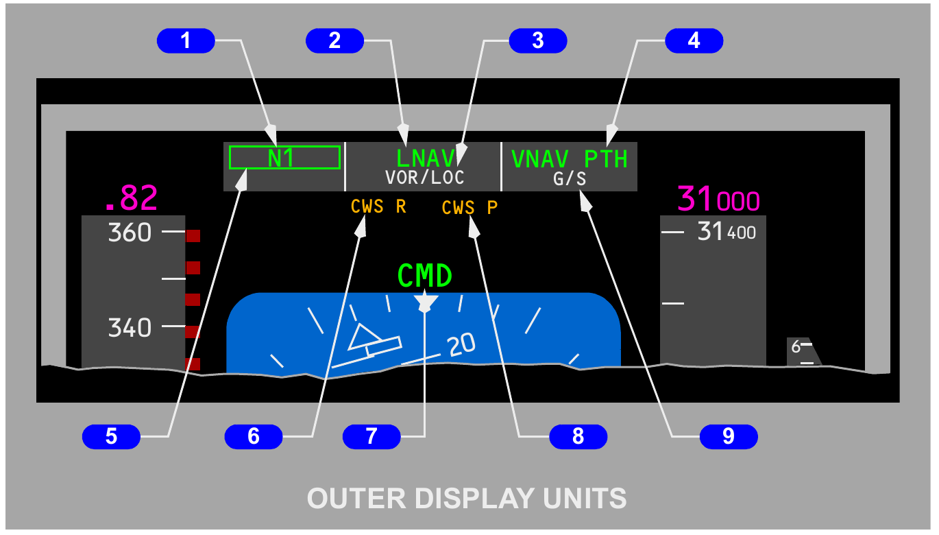
| FMA area | Meaning | Typical entries |
|---|---|---|
| Thrust | Autothrottle command | N1, MCP SPD, FMC SPD, RETARD, ARM |
| Roll | Lateral guidance | HDG SEL, LNAV, VOR/LOC, FAC |
| Pitch | Vertical guidance | TO/GA, VNAV, ALT HOLD, V/S, G/S |
| Status | Autopilot or flight-director state | CMD, CWS P, CWS R, FD, SINGLE CH |
STAB OUT OF TRIM is an autopilot warning and appears only while an autopilot is engaged. It means the stabilizer is not keeping pace with sustained elevator demand. The message is not a normal trim-position indication.
The mode control panel
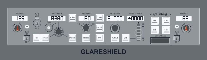
The MCP is the short-term control surface for the automatic flight system. Its windows hold targets while its mode switches tell the computers how to pursue them.
Speed selection
The IAS or MACH window permits manual selection from 100 knots through Vmo, and from Mach .60 through Mmo. The display normally changes automatically between IAS and Mach at about flight level 260. The changeover switch permits a manual change whenever a displayed value is available.
In VNAV, speed intervention allows the crew to replace the FMC target with a selected MCP value without leaving VNAV. The IAS or MACH display is blank when the FMC owns the speed target in FMC SPD, and during the normal blanking cases for VNAV and the two-engine go-around logic. A speed-limit symbol flashes when the selected command is outside the speed that the system can use.
Heading and bank limit
The heading window displays the magnetic heading selected with the heading knob. HDG SEL turns in the direction commanded by the selector. The bank-angle selector offers 10, 15, 20, 25 and 30 degrees. Its limit applies to heading-select manoeuvres and can reduce bank for passenger comfort or manoeuvring margin.
Altitude and vertical speed
The altitude window starts at zero and extends through 50,000 feet. Each selection step changes the target by 100 feet. The selected altitude is a capture boundary for many pitch modes and an intervention reference for VNAV. The vertical-speed window covers 7,900 feet per minute down to 6,000 feet per minute up. Selection changes in 50-foot-per-minute increments below 1,000 feet per minute and in 100-foot-per-minute increments at greater rates.
| Control | Range or choices | Operational use |
|---|---|---|
| IAS or MACH | 100 knots to Vmo; Mach .60 to Mmo | Selected speed and VNAV speed intervention |
| Bank limit | 10, 15, 20, 25 or 30 degrees | Limits HDG SEL bank |
| Altitude | 0 to 50,000 feet, 100-foot steps | Target and capture altitude |
| Vertical speed | Down 7,900 to up 6,000 feet per minute | Selected climb or descent rate |
Autopilot and control wheel steering
CMD lets an FCC move the controls to follow AFDS commands. CWS lets the pilot establish an attitude through control pressure and then asks the autopilot to hold the released attitude.
Engagement conditions
For autopilot engagement, neither pilot should apply force to the control wheel and the STAB TRIM AUTOPILOT cutout switch must be NORMAL. Pressing an A or B CMD switch engages that autopilot when the conditions are satisfied. Except during a dual-channel approach, only one autopilot can remain engaged. Two independent electrical generators are required for dual-autopilot operation.
The autopilot disengage bar prevents engagement when lowered. Normal disengagement is made with either control-wheel disengage switch. The autopilot can also disengage following significant system failures, loss of necessary inertial or electrical inputs, stabilizer-trim interruption, manual control override, or a mode event designed to remove it.
Warnings and reset
An unexpected autopilot disconnect produces a flashing red A/P light and an aural warning. Pressing either disengage switch silences the warning and changes the light from flashing to steady. A second press clears the steady light. An amber A/P light identifies an autopilot degradation rather than the normal red disconnect warning.
CWS pitch and roll
CWS P and CWS R can engage separately. In control wheel steering, applied force changes pitch or bank. When the force is released, the autopilot holds the new attitude. Releasing the wheel at 6 degrees of bank or less causes roll control to level the wings and then hold the existing heading.
That automatic heading-hold feature is inhibited below 1,500 feet radio altitude with the landing gear down, after localizer capture in APP, and after VOR capture when true airspeed is 250 knots or less. These exceptions prevent CWS logic from replacing the path guidance needed close to the ground or during a captured approach.
| Selection | Control law | Crew verification |
|---|---|---|
| CMD A or B | FCC follows active pitch and roll modes | CMD status and FMA modes |
| CWS P | Pilot establishes pitch, autopilot holds it | CWS P status |
| CWS R | Pilot establishes bank, autopilot holds it | CWS R status |
| Disengage bar down | Autopilot engagement prevented | No CMD or CWS engagement |
Basic vertical modes
Vertical modes divide the job between pitch and thrust. Knowing which system controls speed and which controls path prevents unstable energy management.
Level change
LVL CHG coordinates pitch with autothrottle modes to reach the MCP altitude while holding selected speed. In a climb, the autothrottle normally commands climb-limit thrust and pitch holds speed. In a descent, the autothrottle commands idle and pitch again holds speed. Altitude-acquire logic captures the selected level as the aeroplane approaches it.
LVL CHG cannot be selected after glideslope capture. The captured glide path has priority and should not be replaced by a basic open climb or descent mode.
Altitude hold
ALT HOLD maintains either the altitude at which it was engaged or the altitude captured by the AFDS. Its reference is an uncorrected barometric altitude. Changing the barometric setting after capture does not move that stored altitude reference. ALT HOLD is also inhibited after glideslope capture.
Vertical speed
V/S commands the selected vertical rate. The autothrottle normally maintains MCP speed, so the crew must monitor whether available thrust and pitch can satisfy both targets. A high descent rate with a low selected speed can create an excessive pitch demand. A large climb rate can consume airspeed if thrust is insufficient.
While ALT ACQ is active, V/S can arm after the MCP altitude is moved more than 100 feet from the captured target. V/S is inhibited after glideslope capture. Selecting a new vertical mode must therefore be followed by an FMA check and an energy check.
| Pitch mode | Pitch controls | Typical thrust or speed relationship |
|---|---|---|
| LVL CHG climb | Selected speed | Autothrottle uses climb-limit thrust |
| LVL CHG descent | Selected speed | Autothrottle uses idle thrust |
| V/S | Selected vertical rate | Autothrottle normally controls speed |
| ALT HOLD | Captured barometric reference | Autothrottle controls speed as applicable |
| G/S | Captured ILS glide path | Basic modes are inhibited where required |
VNAV and altitude intervention
VNAV connects the FMC vertical profile to AFDS pitch and autothrottle commands. It manages climb, cruise and descent only through a valid active route and completed performance data.
Arming and engagement
VNAV can be armed on the ground when the flight plan and performance entries are valid and both flight-director switches are ON. After takeoff it becomes active at 400 feet above ground level. In flight, selection engages an appropriate VNAV pitch mode when FMC guidance is available.
VNAV ends when the glideslope is captured or when the active LNAV route terminates. A route discontinuity, invalid performance solution or another incompatible guidance condition can also require direct crew action.
Three VNAV ideas
| Mode idea | What is controlled | Crew focus |
|---|---|---|
| VNAV SPD | Pitch maintains the FMC or intervened speed | Check thrust mode and altitude constraint |
| VNAV PTH | Pitch follows the computed vertical path | Monitor speed and path deviation |
| VNAV ALT | Flight is constrained by MCP altitude | Set and confirm the next cleared altitude |
The MCP altitude window remains a hard crew-controlled boundary. VNAV cannot climb above or descend below it. The crew must set the cleared altitude before commanding an FMC vertical change.
Intervention controls
Speed intervention opens the MCP speed window and lets the selected speed replace the FMC speed while VNAV remains engaged. Altitude intervention changes how VNAV treats certain FMC altitude constraints and can initiate a VNAV descent when the required conditions are met. Neither control removes the need to verify the new FMA and the clearance limit.
When VNAV PTH is level, its minimum-speed reversion is not available. That detail matters during level path segments because the system may not abandon the path mode to recover speed. The crew must monitor the speed trend and intervene early.
Lateral modes and approach arming
Lateral guidance ranges from simple heading control to FMC path tracking and radio-course capture. Each mode has entry conditions that must be satisfied before capture.
LNAV on the ground
LNAV may be armed before takeoff when the origin runway is part of the active route and the first active track differs from runway heading by no more than 5 degrees. Both flight directors must be ON, and LNAV must be selected before TO/GA. When armed, LNAV becomes active at 50 feet radio altitude.
LNAV in flight
Within 3 nautical miles of the active route, LNAV can engage from any heading. Farther away, the intercept angle may not exceed 90 degrees. Its projected course must meet the active leg before the active waypoint. LNAV is white while armed and green while engaged.
LNAV can disengage at the end of the active route, at a route discontinuity, when another lateral mode such as HDG SEL is selected, or when required path criteria are lost. RESUME OWN NAVIGATION is an ATC phrase, not an AFDS mode; the crew still selects and verifies an appropriate lateral mode.
VOR or localizer capture
VOR/LOC can capture a selected radio course from LNAV, HDG SEL or CWS R. Localizer capture occurs no later than half-scale deviation. When a localizer frequency is selected, the radio system changes to the appropriate ILS antenna arrangement. Without the required switching, localizer capture is inhibited.
APP mode
APP arms localizer and glideslope capture. One navigation receiver is sufficient for a single-channel approach. Dual operation requires both receivers tuned to the ILS and both autopilots selected to CMD by 800 feet radio altitude. Glideslope capture is permitted only after localizer capture and occurs at about two-fifths of a dot from the beam.
This configuration also supports integrated approach navigation. FAC supplies lateral guidance and G/P supplies vertical guidance for an FMC approach. B/CRS is available for an appropriate back-course operation. These modes do not turn a nonprecision procedure into an ILS and must be monitored against the published approach.
Autothrottle operation
The autothrottle moves each thrust lever through its own servo. It follows the active thrust mode, but the crew remains responsible for thrust, speed and lever agreement.
Arming and modes
Placing the A/T arm switch to ARM makes the system available. The FMA then tells the crew whether it is commanding a thrust limit, a speed, a takeoff or go-around setting, idle, retard, thrust hold, or no active servo command. The system can operate with the electronic engine controls in ON or alternate mode.
| FMA mode | Primary meaning |
|---|---|
| N1 | Thrust levers command the active N1 limit. |
| MCP SPD | Thrust levers maintain the selected MCP speed. |
| FMC SPD | Thrust levers maintain the FMC speed target. |
| THR HLD | Servos release the levers so thrust can be held or adjusted without servo opposition. |
| ARM | No active thrust command, but the system remains armed. |
| RETARD | Thrust levers are driven towards idle during the landing flare. |
Lever agreement and disconnect
In normal operation the thrust levers should remain closely aligned, generally within about one knob width. A significant split can reveal unequal servo command or a fault. Certain mode and power conditions can disconnect the autothrottle when lever disagreement exceeds about 10 degrees.
The system disengages if the A/T arm switch is moved OFF, either thrust-lever disconnect switch is pressed, a monitored fault occurs, or the normal landing logic removes it about two seconds after touchdown. The red A/T warning flashes for an unexpected disconnect, but it does not illuminate for the normal automatic disconnect after landing.
Manual lever movement can override the servo in most active modes. The pilot should make a deliberate correction, then verify that the resulting thrust mode and lever behaviour remain appropriate. Never infer commanded thrust from lever position alone.
Takeoff and climb sequence
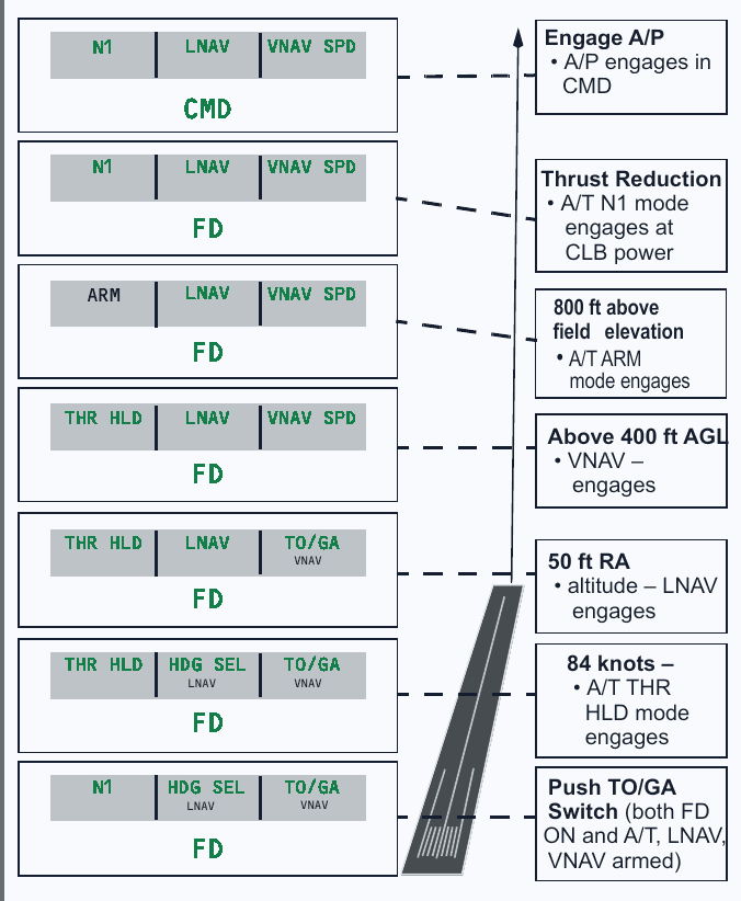
Takeoff guidance is a timed handover from TO/GA and N1 to the armed lateral and vertical modes. The FMA sequence is the safest way to understand it.
Before and during the roll
With both flight directors ON and the desired lateral and vertical modes armed, pressing either TO/GA switch engages takeoff guidance and commands the takeoff thrust setting. At approximately 84 knots, THR HLD replaces N1. The servo releases the thrust levers, protecting against unwanted movement during the high-speed part of the roll.
Flight-director pitch guidance initially commands about 10 degrees nose down until approximately 60 knots. It then commands about 15 degrees nose up for rotation. After lift-off it holds that takeoff attitude until a climb rate is established, then commands the speed target, normally V2 plus 20 knots for an all-engine takeoff.
After lift-off
If armed, LNAV engages at 50 feet radio altitude. VNAV may engage above 400 feet above ground level. At 800 feet above field elevation, the autothrottle changes to ARM. At the programmed thrust-reduction point it commands climb thrust. The autopilot can then be engaged in CMD when the normal engagement conditions are met.
For an engine failure during the takeoff sequence, pitch guidance targets V2 when the failure occurs on the ground, or the speed at lift-off if it is greater. When speed is already between V2 and V2 plus 20, that speed becomes the target; higher speed is normally limited to V2 plus 20.
Precision approach, flare and touchdown
This aircraft uses a dual-autopilot, fail-passive approach through flare and touchdown. It does not provide automatic rollout, so the crew takes manual control after touchdown.
Building the dual approach
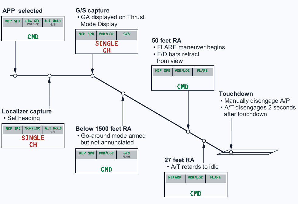
APP may initially use one ILS receiver and one autopilot. For a dual-channel approach, both ILS receivers must be tuned and both autopilots must be in CMD by 800 feet radio altitude. Localizer capture occurs no later than half-dot deviation. Glideslope capture follows localizer capture and occurs near two-fifths dot displacement.
Below 1,500 feet radio altitude after localizer and glideslope capture, the second autopilot couples. The monitoring test runs, FLARE arms and SINGLE CH extinguishes. If FLARE has not armed by approximately 350 feet radio altitude, both autopilots disengage. The configuration is fail-passive: a single failure should leave the aeroplane in a stable condition for the crew to take over, rather than continue with automatic rollout.
Flare and touchdown
Flare manoeuvring begins near 50 feet radio altitude and the flight-director bars retract. The autothrottle annunciates RETARD and drives the thrust levers towards idle at about 27 feet radio altitude. It disengages automatically about two seconds after touchdown.
The crew manually disengages the autopilot after touchdown and completes the rollout manually. Do not expect a ROLLOUT mode, LAND 3 or LAND 2 annunciation from this configuration. Those indications belong to different automatic-landing installations.
| Point | Expected event | Crew check |
|---|---|---|
| By 800 feet RA | Both ILS receivers tuned and both autopilots in CMD | Dual approach established |
| Below 1,500 feet RA | Second autopilot couples and FLARE arms | SINGLE CH extinguishes |
| About 350 feet RA | FLARE must already be armed | If not, autopilots disengage |
| About 50 feet RA | Flare begins and FD bars retract | Monitor attitude and path |
| About 27 feet RA | RETARD drives thrust towards idle | Guard thrust levers |
| After touchdown | A/T disconnects after about two seconds | Disengage A/P and roll out manually |
Go-around, windshear and speed protection
TO/GA supplies go-around guidance, but the crew must distinguish the first reduced command, the second full command and the special guidance used for windshear escape.
Go-around logic
Go-around mode is available below 2,000 feet radio altitude. Above that height it remains available when the flaps are not up or when glideslope is captured. Pressing a TO/GA switch gives go-around thrust and flight-director commands. A second press commands the full available go-around thrust setting.
Roll guidance initially maintains the existing ground track. Pitch guidance commands a climb appropriate to the go-around condition and speed. With one engine inoperative, flight-director pitch guidance initially commands about 13 degrees nose up. The crew then selects or verifies the required lateral and vertical modes for the missed approach.
Windshear guidance
During a takeoff or go-around windshear escape, flight-director guidance holds the existing target until a positive vertical trend of approximately 600 feet per minute is achieved. It then commands about 15 degrees nose up. If vertical speed subsequently reverses, guidance responds to recover the climb. The pilot must still apply the published escape technique and respect stall warning.
On an ILS approach, the autopilot and flight director try to hold the selected attitude or glideslope and do not use angle-of-attack or stick-shaker inputs as an automatic escape law. A windshear warning therefore requires prompt pilot intervention rather than reliance on ordinary approach tracking.
Speed protection and command limits
AFDS command limiting is independent of the stall and overspeed warning systems. The minimum selectable speed is approximately 1.3 times stall speed. A command above the applicable placard limit or below the minimum is rejected and the MCP speed-limit symbol flashes. When speed rises about 15 knots above the minimum, the underspeed condition is removed.
Minimum-speed reversion can replace V/S or CWS P with LVL CHG, and can leave VNAV PTH where its path is descending. It is not available with the autothrottle off while ALT HOLD is engaged, after glideslope capture, or during a level VNAV PTH segment. These exclusions explain why the crew must monitor trend rather than expect universal automatic recovery.
| Condition | Automatic-flight response | Crew priority |
|---|---|---|
| First TO/GA selection | Go-around thrust and guidance | Verify FMA and positive climb |
| Second TO/GA selection | Full go-around thrust command | Control speed and configuration |
| Minimum speed in V/S or CWS P | Possible reversion to LVL CHG | Confirm mode and recover energy |
| Windshear during ILS tracking | No automatic angle-of-attack escape law | Intervene and fly the escape guidance |