
Fire detection architecture
Fire protection combines detection, flight deck warning, system isolation and extinguishing. The engine system also distinguishes a lower temperature overheat from a higher temperature fire condition.
What is protected
The engines have overheat and fire detection plus extinguishing. The APU has fire detection and extinguishing. The main gear wheel well has detection but no installed extinguishing system. Each cargo compartment has smoke detection and a shared suppression system. Each lavatory has local smoke detection and an automatic waste-bin extinguisher.
| Area | Detection arrangement | Extinguishing arrangement | Normal power source |
|---|---|---|---|
| Each engine | Two overheat and fire loops | Either of two engine bottles can feed either engine | Detection: battery bus. Extinguishing: hot battery bus |
| APU | One self-monitoring fire loop | One APU bottle | Detection: battery bus. Extinguishing: hot battery bus |
| Main wheel well | One fire loop | None | AC transfer bus 2 and battery bus |
| Forward and aft cargo compartments | Dual-loop smoke detection in each compartment | Two bottles routed to the selected compartment | Detection: DC buses 1 and 2. Suppression: hot battery bus |
Two loops on each engine
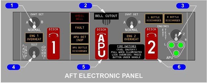
Each engine carries loop A and loop B. Either loop can detect both overheat and fire, but the fire threshold is above the overheat threshold. With the OVHT DET selector at NORMAL, the alerting logic normally requires both loops to agree. This prevents one defective detector path from creating a false warning.
If one loop fails while NORMAL is selected, the system automatically uses the remaining healthy loop as a single-loop detector. The crew receives no indication merely because the logic has changed to that surviving loop. If the remaining loop also fails, the FAULT light identifies that the engine detection system is inoperative. Selecting A or B deliberately monitors only that loop; the unselected loop is not watched. A failure of the selected loop illuminates FAULT.
Overheat and fire indications
An engine overheat lights both MASTER CAUTION lights, the OVHT/DET annunciator and the related amber ENG OVERHEAT light. An engine fire sounds the fire bell, lights both MASTER FIRE WARN lights and illuminates the related fire switch. The associated engine overheat indications also appear. The ENG OVERHEAT light or illuminated fire switch remains on until detector temperature falls below its onset threshold.
Engine and APU extinguishing
The red fire switch is both an isolation control and the selector for bottle discharge. Pulling it changes the protected system first; rotating it releases extinguishing agent.
Engine fire switch
Engine fire switches are normally locked down. An illuminated engine fire switch or the related ENG OVERHEAT light unlocks the switch. The override beneath the handle permits manual unlocking when required.
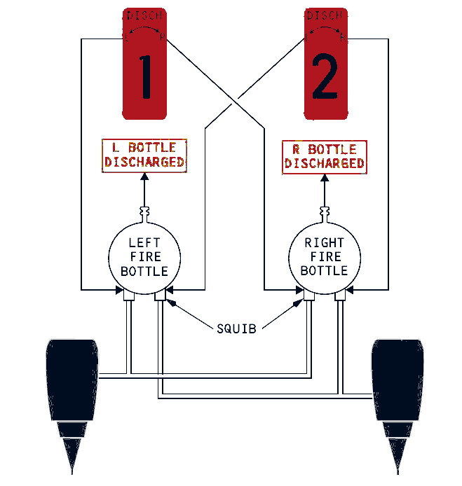
Pulling an engine fire switch closes two fuel barriers, one at the engine and one at the spar. It shuts the engine bleed and corresponding wing anti-ice valves. The action disconnects the generator through its control relay and breaker, stops hydraulic-fluid supply to the engine-driven pump, suppresses that pump's LOW PRESSURE indication, disables the related thrust reverser, prepares one squib on each engine bottle and enables rotation of the switch.
Bottle indication
After rotation, the appropriate L or R BOTTLE DISCHARGED light normally appears within a few seconds. The amber light means the bottle has discharged or its pressure is low. It does not, by itself, prove that the fire is out.
APU detection and warning
The APU uses one detector loop. It continuously monitors its own fault circuit, so a failed loop lights APU DET INOP. An APU fire sounds the flight deck fire bell, lights both MASTER FIRE WARN lights and the APU fire switch, and automatically shuts down the APU. On the ground, a horn sounds and a warning light flashes at the main wheel well control panel. The ground horn may be silenced without cancelling the steady fire indication.
APU fire switch and bottle
A mechanical lock normally holds the APU fire switch in the down position; illumination releases that lock. Pulling it backs up automatic shutdown, removes power from the fuel solenoid, shuts the APU's fuel and bleed valves, closes the inlet door, disconnects its generator, prepares the bottle squib and permits switch rotation. Turning the switch either way releases the single APU bottle. The APU BOTTLE DISCHARGED light appears after a few seconds when discharge has occurred or bottle pressure is low.
The main wheel well panel provides an external APU fire control handle and bottle discharge control. That discharge control is armed only after the external fire handle is pulled. It allows ground personnel to isolate and extinguish an APU fire without entering the flight deck.
Wheel well and lavatory protection
The wheel well and lavatories use very different protection philosophies. The wheel well warns the crew, while the lavatory combines a local detector with an automatic extinguisher in the waste-bin area.
Main wheel well
A single detector loop monitors the main gear wheel well. When its temperature reaches the fire threshold, the audible fire bell operates, the pair of MASTER FIRE WARN lights illuminate and the red WHEEL WELL light comes on. The light remains illuminated until detector temperature falls below the onset value.
There is no built-in wheel well extinguisher. Fire detection is not installed in the nose gear well. These two facts matter because the warning identifies a condition that cannot be treated by selecting an onboard wheel well bottle.
Lavatory smoke detection
Each lavatory has a ceiling-mounted smoke detector that gives an aural warning and illuminates a red status light at the detector. In this configuration there is no flight deck indication for lavatory smoke. When smoke clears, the installed detector resets automatically.
Waste-bin extinguisher
A heat-activated extinguisher is mounted below the sink and directs agent through two nozzles towards the towel-disposal container. Operation is automatic when the local heat threshold is reached. The flight deck receives no extinguisher discharge indication.
The bottle has a temperature indicator placard and the nozzles give a physical condition cue. A white temperature indicator is normal, while black shows exposure to high temperature. Flat black nozzle ends are normal; an aluminium appearance indicates discharge.
| Protection | Crew indication | Extinguishing |
|---|---|---|
| Main wheel well | Fire bell, MASTER FIRE WARN and WHEEL WELL light | No installed system |
| Lavatory smoke | Local horn and red detector light | Not part of the smoke detector |
| Lavatory waste bin | No flight deck discharge indication | Automatic, heat activated |
Cargo smoke detection
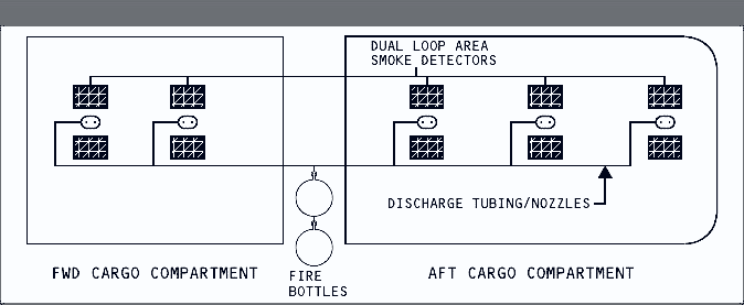
The forward and aft cargo compartments each use dual-loop area smoke detection. A separate control selects the compartment that will receive extinguishing agent.
Normal dual-loop logic
Under normal conditions, both detector loops in a cargo compartment must sense smoke before the system announces a fire. Separate DC sources support the two loops. If one loop loses power, the logic automatically converts to single-loop detection. If a detector fails, the crew can select the serviceable loop manually with the corresponding DET SELECT switch.
The DETECTOR FAULT light indicates that one or more detectors in a selected loop has failed. Individual detector faults are found through the manually initiated cargo fire test, rather than continuous identification of each detector.
Cargo fire warning
A confirmed forward or aft cargo warning sounds the fire bell, lights both MASTER FIRE WARN lights and illuminates the red FWD or AFT cargo fire warning light. The cargo panel is not tied into MASTER CAUTION for its panel lights.
After the initial warning, a compartment light may go out, remain on or illuminate again during the flight. A renewed indication reactivates the two MASTER FIRE WARN lights and the audible bell. The changing light does not prove that the compartment is safe, because smoke may move within the compartment while suppression continues.
| Condition | Detector logic | Flight deck consequence |
|---|---|---|
| Both loops healthy | Both selected loops must detect smoke | Normal dual-loop confirmation |
| Power lost to one loop | Automatic single-loop operation | The surviving loop can trigger the alert |
| Detector failure | Select A or B to use the healthy loop | DETECTOR FAULT identifies the abnormal system |
| Warning reappears after initial alert | Smoke is detected again | Fire bell and both MASTER FIRE WARN lights reactivate |
Cargo suppression and system tests
Cargo fire protection is designed to suppress combustion until the aircraft can land and the compartment can be dealt with on the ground. The first bottle acts quickly; the second maintains a lower flow for a much longer period.
Arming and discharge
Pressing FWD ARM or AFT ARM configures the bottle plumbing for that compartment. Pressing DISCH then releases the full contents of the first bottle into the selected compartment. The second bottle is metered at a reduced rate to extend suppression time.
For this configuration, the combined design provides 195 minutes of suppression. This consists of 180 minutes allowed for reaching an aerodrome plus 15 minutes for a missed approach, another approach, landing and passenger unloading. The cargo DISCH light indicates that a bottle has discharged or pressure is low, and it may take up to 30 seconds to illuminate.
Disarming the system can disable the later release. Once on the ground, an armed system that has already released bottle one prevents the second bottle from discharging. The system suppresses the fire rather than guaranteeing extinguishment. Smoke can remain or continue until ground firefighters extinguish the source.
Fire and overheat tests
Holding the common test switch at FAULT/INOP checks the engine and APU fault-monitoring circuits. Expected indications include both MASTER CAUTION lights, the OVHT/DET annunciator, FAULT and APU DET INOP.
Holding it at OVHT/FIRE tests both engine detection systems, the APU loop and the main wheel well detector. Expected indications include the fire bell, both MASTER FIRE WARN lights, both MASTER CAUTION lights, OVHT/DET, both engine fire switches, the APU fire switch and both ENG OVERHEAT lights. Available AC power also brings on WHEEL WELL. During a ground test, the external APU horn operates and its wheel well light flashes.
Moving EXT TEST to 1 checks the discharge paths for engine 1 and the APU; position 2 checks engine 2 and the APU. Green EXT TEST lights confirm continuity from the squib circuit. Test indications clear when the spring-loaded controls are released.
Cargo fire test
Holding the cargo TEST switch sends a test signal to forward and aft detection loops and checks bottle squib continuity. A satisfactory test produces the fire bell, both MASTER FIRE WARN lights, the green extinguisher test lights, both FWD and AFT cargo fire lights, and the cargo DISCH light. A DETECTOR FAULT light during the test identifies a failed detector in a selected loop. At release, a delay of up to four seconds may occur while all indications clear together.