
Tanks, capacity and normal fuel feed
This aircraft stores usable fuel in two integral wing tanks and a much larger centre tank. Six AC-powered boost pumps establish the normal feed pattern, while check valves keep flow moving in the intended direction and prevent unwanted transfer between tanks.
Tank arrangement
Main tanks 1 and 2 form part of the left and right wing structure. The centre tank sits between the wing roots and extends into the wing structure. The capacity figures below are approximate usable quantities at level attitude and a reference fuel density of 0.8029 kilograms per litre.
| Tank | Usable volume | Approximate mass |
|---|---|---|
| Main tank 1 | 4,876 litres | 3,915 kg |
| Main tank 2 | 4,876 litres | 3,915 kg |
| Centre tank | 16,273 litres | 13,066 kg |
| Total | 26,025 litres | 20,896 kg |
Why the centre tank feeds first
Every tank has two electrically driven pumps. Centre-tank pumps deliver at a higher pressure than the main-tank pumps, so centre fuel supplies both engine manifolds while all six pumps are operating. As the centre quantity approaches zero, the engines transition to fuel from their respective main tanks.
Each pump has its own pressure sensor. Check valves prevent reverse flow and stop one tank from feeding into another through the common manifolds. This pressure hierarchy creates the normal sequence without requiring the crew to close the main-tank pumps while centre fuel is used.
Nitrogen-enriched air
The nitrogen generation system reduces centre-tank flammability by converting bleed air into nitrogen-enriched air. It starts automatically after takeoff, operates through the airborne phases and remains active briefly after landing. No routine flight-deck action is required.
Automatic shutdown occurs for defined conditions, including loss of an engine in flight, detected cargo or main-deck smoke or fire, left pack overheat, an open centre-tank refuelling valve, or ground operation outside test mode. A wheel-well indicator shows green for operational, blue for degraded and amber for inoperative; no illuminated light also signifies inoperative.
Fuel control panel, pumps and crossfeed
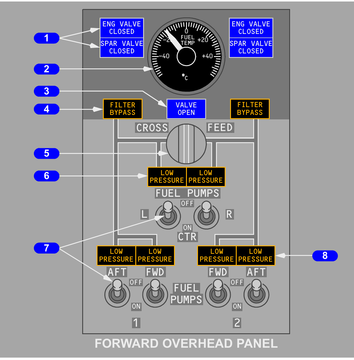
The overhead panel brings the feed system into one view: pump pressure, crossfeed position, filter condition, valve status and main-tank fuel temperature. Reading the colour and brightness of each light is as important as reading its label.
Pump lights and caution logic
| Indication | When illuminated | System-level alert |
|---|---|---|
| Centre LOW PRESSURE | Switch ON with inadequate pump discharge pressure | One continuously illuminated light for 10 seconds triggers MASTER CAUTION and FUEL |
| Main LOW PRESSURE | Pump pressure low or its switch OFF | Both lights in one tank trigger MASTER CAUTION and FUEL; one appears on recall |
| FILTER BYPASS | Filter contamination is approaching bypass | Amber attention to the affected engine fuel filter |
A centre-pump low-pressure light is extinguished when its switch is OFF. Moving a centre-pump switch OFF resets that pump's automatic shutoff logic; returning it to ON lets the pump run again until low-pressure logic or the switch stops it. With little fuel in a tank, attitude and inlet location can make a LOW PRESSURE light flicker. Centre-pump flicker can persist for several minutes near empty.
Crossfeed
CROSSFEED closed keeps the left and right engine-feed manifolds isolated. Opening it connects the manifolds, allowing an operating pump in one main tank to supply both engines. Leaving that arrangement in use can create a growing main-tank imbalance.
The blue VALVE OPEN light is dim when the commanded valve is fully open. A bright light means the valve is moving or its actual position disagrees with the selector. The light is out when the valve is closed.
Valve and filter indications
Each engine has an engine fuel shutoff valve and a spar valve. Their blue CLOSED lights are dim when the related valve is closed, bright during travel or command disagreement, and extinguished when open. Pulling the engine fire switch or moving the start lever to CUTOFF closes both valves for that engine.
Suction feed, scavenge and APU supply
Boost pressure is the normal source of fuel flow, but the plumbing also supports suction feed, centre-tank scavenging and APU supply. Each path has a different purpose and limitation.
Main-tank suction feed
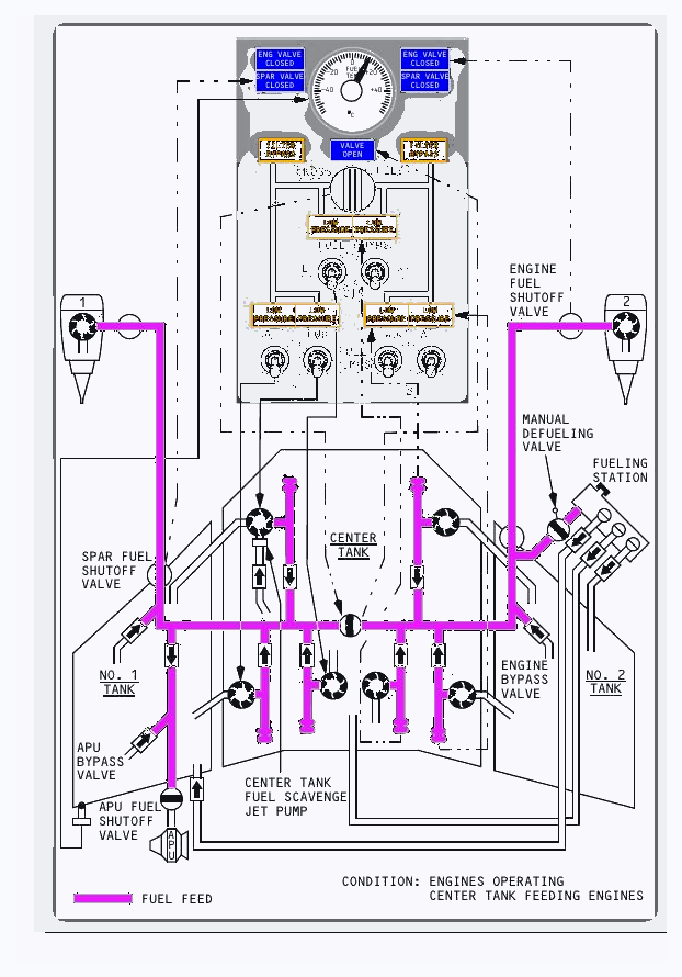
If main-tank pump pressure is unavailable, each engine can draw from its corresponding tank through a bypass line around the pumps. Suction feed becomes less dependable with altitude because reduced ambient pressure releases dissolved air from the fuel. Air collecting in the line can restrict flow, producing thrust loss or flameout at high altitude.
After level-off, the amount of dissolved air gradually falls. The time depends on altitude, fuel temperature and fuel type. Suction feed at cruise power may become possible after this process, but the approved non-normal procedure remains controlling.
Centre-tank scavenge
With the forward pump switch for main tank 1 ON, a jet pump automatically transfers residual centre-tank fuel into main tank 1. Transfer begins when the quantity in main tank 1 has fallen to about half. Once scavenging starts, it continues for the rest of the flight.
APU feed
When AC fuel pumps are running, the APU receives fuel through the left side of the common manifold. With those pumps off, it can draw by suction from main tank 1. The APU fuel shutoff valve and bypass plumbing provide the required isolation and alternate path.
Fuel temperature
The overhead gauge displays temperature sensed in main tank 1 and uses AC power. The reading represents the monitored tank, not an average of all three tanks.
Quantity indications and fuel alerts
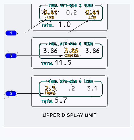
The upper display shows usable quantity for each tank and the total. Amber LOW, CONFIG and IMBAL messages describe three different problems: too little fuel in a main tank, centre fuel with no centre pumps selected, or unequal main-tank quantities.
Quantity display and accuracy
Tank quantities remain available with AC or DC electrical power, and the total is shown below the three individual values. The system calculates usable fuel in each tank. Indicated quantity may differ from actual fuel by as much as 2.0 percent on the ground and 2.5 percent in flight.
Alert thresholds for this configuration
| Alert | Appears when | Clears or is inhibited when |
|---|---|---|
| LOW | A related main tank falls below 907 kg | That tank rises to 1,134 kg |
| CONFIG | Either engine runs, centre fuel exceeds 726 kg and both centre-pump switches are OFF | Both engines stop, centre fuel falls below 363 kg, or either centre pump is selected ON |
| IMBAL | Main tanks differ by more than 453 kg | Difference falls to 91 kg; LOW suppresses IMBAL when both conditions exist |
IMBAL appears beneath the main tank with the lower quantity and is available both on the ground and in flight for this configuration. The alert thresholds include hysteresis, so a message does not repeatedly appear and disappear at a single value.
Refuelling, defuelling and ground measurement
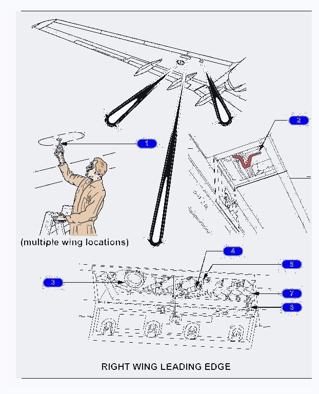
The right-wing single-point station supports rapid refuelling, defuelling and fuel transfer on the ground. Independent panel indications and manual measuring sticks provide ways to command, monitor and cross-check the operation.
Single-point station
Opening the refuelling door powers the servicing system and panel lights through a proximity-controlled relay. Pressure opens a selected tank valve when the battery is ON and the door is open. An automatic shutoff closes each tank valve when that tank reaches full.
A blue valve-position light illuminates when its switch is OPEN and the related tank is not yet full. It extinguishes when the tank is full with the switch still open, or whenever the switch is CLOSED. A mechanical override can open a solenoid-operated valve if fuel pressure is available.
Panel test and quantity
TEST GAGES checks the servicing-panel quantity indications. FUEL DOOR SWITCH BYPASS can energise the panel after failure of the normal door-controlled relay. Separate indicators show usable quantity in tanks 2, centre and 1.
Defuelling and transfer
The manual defuelling valve is positioned outboard of engine 2. Opening it connects the engine-feed plumbing to the servicing station for defuelling or tank-to-tank ground transfer. The valve is closed to isolate those systems during normal operation.
Manual measuring sticks
Each main tank has six measuring sticks and the centre tank has four. A stick is withdrawn and latched magnetically to its internal float. Fuel depth is read where the stick meets the wing skin, then converted using the approved tables and aircraft attitude.