
Radio tuning panels
A radio tuning panel can control the installed VHF or HF radio. It keeps one frequency active while another is prepared in standby, which allows an orderly change without losing the frequency presently in use.
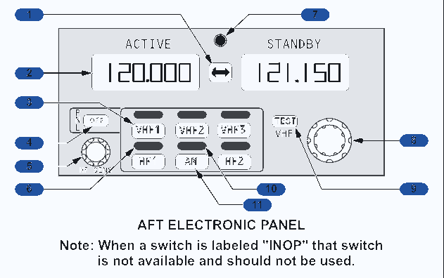
Active and standby windows
The ACTIVE window shows the frequency presently tuned in the selected radio. The STANDBY window carries the prepared or previously active frequency. Pressing the transfer switch swaps the two entries and tunes the radio to the newly active value.
This configuration displays six digits for 8.33 kHz channel spacing. The outer frequency selector changes the megahertz portion, while the inner selector changes the remaining digits. The first displayed digit remains 1. Pressing a radio tuning switch chooses the VHF or HF set to be controlled.
Panel controls and lights
| Control or indication | Practical meaning |
|---|---|
| Radio tuning light | White illumination identifies the selected radio. |
| Offside tuning light | Another panel is tuning the normally associated radio, or this panel is controlling a radio normally assigned elsewhere. |
| OFF switch | Disconnects that panel from the communication radios. |
| HF SENS | Changes receiver sensitivity for the on-side HF radio. |
| VHF TEST | Opens automatic squelch so receiver noise can be heard and weak reception can be checked. |
| AM light and switch | The light is on for HF amplitude modulation and off for upper sideband. |
Failure displays
PANEL with FAIL indicates a failed radio tuning panel. FAIL in both frequency windows identifies failure of the selected radio. A frequency may remain visible even when its radio is unavailable, so a display alone is not proof of serviceability. A switch marked INOP is not installed for use and must not be selected.
Normal audio control
Each crew-station audio system separates transmission choice from receiver monitoring. One source can be selected for speaking while several other sources are listened to at individually chosen volumes.
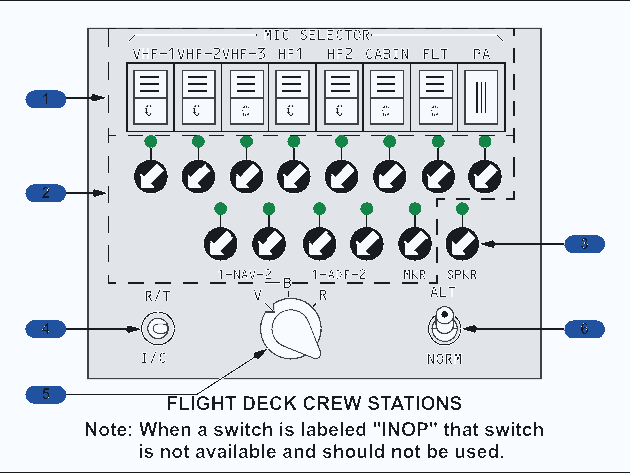
Independent crew stations
Audio control panels are installed for the Captain, First Officer and First Observer. Each station has an independent audio channel and separate circuit protection within a common remote electronics unit. A second observer position, when occupied, has headphone audio tied to the First Observer's selection rather than another complete ACP.
Only one microphone selector can be active at a station. Selecting another automatically cancels the first. Reception from the chosen transmitter remains available even when its receiver selector is not separately pressed. By contrast, several receiver selectors can be on at the same time, and rotating each control adjusts its contribution to the headset and speaker.
Speaker and warning audio
The Captain and First Officer have overhead speakers; the observer does not. Receiver controls set headset volume, while both the receiver control and SPKR control influence loudspeaker volume. Ground-proximity, altitude-alert, collision-avoidance and predictive-windshear audio is delivered at a fixed level that the crew cannot turn down or deselect.
Normal push-to-talk operation by either pilot mutes the two flight-deck speakers to prevent acoustic feedback. Transmission from an oxygen-mask microphone does not mute them.
Microphones and selector logic
Hand and boom microphones connect at the crew stations, and each oxygen mask contains its own microphone. On this installation, opening the left oxygen-mask panel door enables the mask microphone and disables the boom. Closing that door and pressing RESET or TEST restores the boom microphone and removes the mask microphone from service.
The control-wheel or panel PTT keys the mask or boom microphone according to the R/T selection. Moving the PTT to I/C bypasses the chosen radio transmitter and talks directly over the flight interphone. A hand microphone uses its own PTT and is unaffected by this mask or boom logic. The glareshield MIC switch performs the same transmit-keying function as the control-wheel switch for the pilot's selected system.
Navigation-audio filter
| Filter position | Audio passed from NAV and ADF |
|---|---|
| V | Voice audio |
| B | Voice plus coded range or identifier audio |
| R | Coded range or station-identifier audio |
Degraded audio operation
ALT is a reversion path for an ACP or remote-electronics fault. It restores a basic radio path, but many normal selectors, alerts and interphone functions disappear at the affected station.
What ALT changes
Moving ALT or NORM to ALT bypasses normal digital control for that crew station. The ACP selections no longer govern the remote unit. One predetermined VHF radio is connected for both reception and transmission, heard through the headset at a fixed volume.
| Affected station | Radio retained in ALT |
|---|---|
| Captain's station | Radio VHF 1 |
| First Officer's station | Radio VHF 2 |
| Observer's station | Radio VHF 1 |
Functions that are lost
The microphone selectors and receiver switches no longer work normally. The speaker and its control are unavailable. Flight and service interphone cannot be reached through the affected ACP, so the I/C position also has no function there. Passenger address cannot be selected through that ACP.
The hand microphone is not usable in degraded mode on this installation. The boom and oxygen-mask microphones remain available and can be keyed with the control-wheel MIC position or ACP R/T position.
Warning-audio consequence
The affected audio side does not reproduce altitude alert, ground-proximity or windshear warnings. The unaffected pilot's side continues to provide those warnings if its own ALT mode has not been selected. This makes a dual ALT selection especially significant.
A separately installed service-interphone handset or PA microphone on the control stand can still be used because it does not depend on the failed ACP control path.
Interphone, passenger address and calls
The flight interphone, service interphone, passenger-address system and call system share crew interfaces, but each serves a different audience and follows a distinct priority.
Flight and service interphone
The flight interphone is a private network for flight-deck crew. Ground personnel can join it through the jack at the external-power receptacle. Pilots can transmit through a control-wheel or glareshield PTT, while any station with an ACP can select the flight-interphone path and use a standard microphone.
The service interphone connects the flight deck, cabin crew and ground service positions. Cabin crew use their handsets, and picking one up connects it to the system. Selecting the service-interphone switch adds the external maintenance jacks to that network.
Passenger-address priority
PA audio is distributed to cabin speakers, including those in passenger-service units, galleys, lavatories and entry areas. Sources are prioritised so an urgent flight-deck announcement cannot be masked by entertainment. The dedicated flight-deck PA microphone connects directly to the PA path and bypasses the ACPs.
| Priority | Source | Effect |
|---|---|---|
| 1, highest | Flight deck with PA selected, or the dedicated flight-deck PA microphone | Overrides cabin announcements, recorded programmes and music. |
| 2 | Cabin-crew handset | Overrides recorded programmes and entertainment. |
| 3 | Recorded announcement and music system | Manual recordings outrank automatic recordings, and both outrank music. |
Call indications
| Call direction | Visual cue | Aural cue |
|---|---|---|
| Flight deck to cabin crew | Pink master-call lights | Two-tone cabin chime |
| Flight deck to ground | No separate cockpit cue required | Horn in the nose-wheel well |
| Cabin crew to flight deck | Call light on the integrated ACP | Single high-tone chime |
| Ground to flight deck | Call light on the integrated ACP | Single high-tone chime |
| Seat-belt or no-smoking sign change | Cabin sign changes state | Single low-tone chime |
The ATTEND switch summons cabin crew. GRD CALL sounds the wheel-well horn while held. These attention signals request communication; the appropriate interphone path must still be used for the conversation.
VHF, HF and SELCAL
Three VHF radios provide the normal short-range voice paths. One HF installation extends communication beyond line of sight, while SELCAL lets the crew monitor without listening continuously to radio noise.
VHF arrangement
Each VHF set is independent and keeps an active and a standby frequency. VHF 1 uses an upper-fuselage antenna. VHF 2 and VHF 3 use lower-fuselage antennas. The lower antennas can suffer multipath interference from nearby vehicles or structures on the ground, while the upper antenna is less exposed to that effect.
HF operation
The installed HF radio can be tuned from any RTP, but receiver sensitivity can be changed only from its on-side panel. Its antenna is in the vertical stabilizer. Selecting a new frequency and keying the transmitter starts antenna tuning, which may produce a steady or intermittent audio tone.
A normal tune can take as long as 7 seconds. A tone that continues beyond 7 seconds indicates unsuccessful tuning and can persist for no more than 15 seconds. The last 100 tuned frequencies are retained in memory, so a repeated frequency can tune so quickly that the tone is barely noticeable.
| Tune-tone behaviour | Interpretation |
|---|---|
| Ends within 7 seconds | Normal antenna matching may be occurring. |
| Continues beyond 7 seconds | The antenna has not tuned successfully. |
| Ends very quickly on a recent frequency | Stored tuning data can shorten the match cycle. |
| Persists to 15 seconds | Maximum failure-tone duration has been reached. |
Selective calling
SELCAL watches selected VHF and HF frequencies for the aircraft's assigned four-letter code. A valid ground call sounds a two-tone chime and illuminates the related call indication on the integrated ACP. Keying a microphone, pressing a control-wheel microphone switch, or moving the R/T or I/C switch to R/T resets that call indication.
Cockpit voice recorder
The cockpit voice recorder stores flight-deck area sound and the separate crew audio feeds. Its automatic power schedule captures the operating period without depending on a routine manual ON selection.
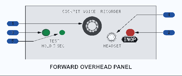
Four channels and 120 minutes
The recorder has four separate channels and retains 120 minutes of audio. New recording continually replaces material older than that period. One channel receives the flight-deck area microphone. The remaining channels receive individual ACP output and transmitted audio for the flight crew and observer.
Power schedule
In AUTO, recorder power begins when the first engine starts. It remains supplied until five minutes have passed following shutdown of the final engine. ON powers the recorder before engine start. Once an engine starts, the switch returns to AUTO and the automatic schedule takes over.
The area microphone follows the same operating trigger: it becomes active with an engine start or with the recorder switch selected ON.
Test and erase installation
Holding the green TEST switch for 5 seconds illuminates its green light when an engine is running or the recorder switch is ON. A test tone can be monitored at the HEADSET jack, which can also be used for playback. The red erase control is marked INOP on this configuration, so flight-deck erasure through that switch is not available.
| Item | Function on this installation |
|---|---|
| Area microphone | Captures ambient flight-deck sound. |
| TEST, held 5 seconds | Runs the monitor check and illuminates the green test light. |
| HEADSET jack | Allows test-tone and recorded-audio monitoring. |
| ERASE | Marked INOP and unavailable for crew use. |
| AUTO | Starts recording with the first engine and stops five minutes after the final engine is shut down. |