
Display architecture and normal arrangement
Six display units turn information from aircraft sensors and computers into two primary flight displays, two navigation displays and the central engine displays. Understanding who generates the data, who formats it and where it appears makes every failure indication easier to interpret.
The six display units
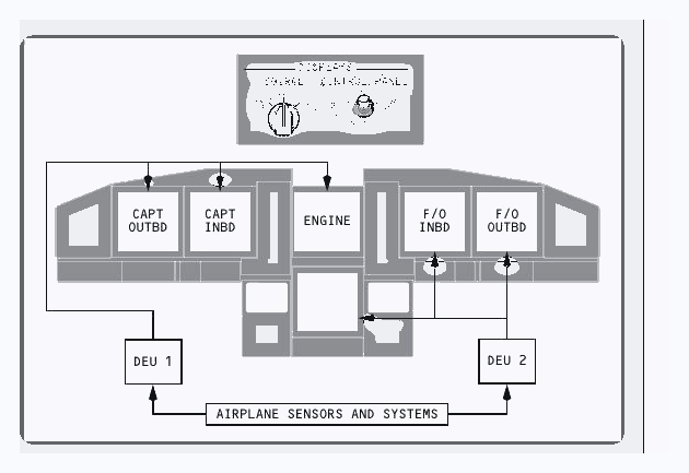
Each pilot normally has an outboard primary flight display, or PFD, and an inboard navigation display, or ND. Two centre units are arranged vertically. The upper centre unit normally carries the primary engine display. The lower unit can show the secondary engine display, system information or another selectable format. The display select panels let the crew choose what the centre units present, but the normal arrangement should be retained unless a procedure calls for another selection.
Two display electronics units, called DEUs, receive sensor and system data, build the display formats and drive the display units. In normal operation, each DEU supplies defined display units. The two sources also monitor one another, which supports automatic reconfiguration after a source failure.
What a PFD and ND do
| Display | Primary job | Typical information |
|---|---|---|
| PFD | Immediate aircraft control and approach guidance | Airspeed, attitude, altitude, vertical speed, heading, flight director, modes, minimums and approach deviation |
| ND | Position, route and navigation awareness | Track, heading, route, waypoints, radio aids, weather radar, terrain, traffic and vertical profile |
| Centre units | Engine and system monitoring | Primary engine indications above, with secondary engine or system information below when selected |
The PFD is organised so attitude remains central, airspeed is to the left and altitude with vertical speed is to the right. Heading and track occupy the lower area. The flight mode annunciations across the top are the authoritative statement of what the automatic flight system is doing.
Colour is information
White normally represents present data, fixed scales or inactive reference information. Magenta identifies selected targets and active flight-management guidance. Green is used for normal cues and some reference data. Amber calls attention to a limit, a disagree condition, a degraded source or a cautionary state. Red is reserved for warnings and operating limits that must not be exceeded.
PFD airspeed indications
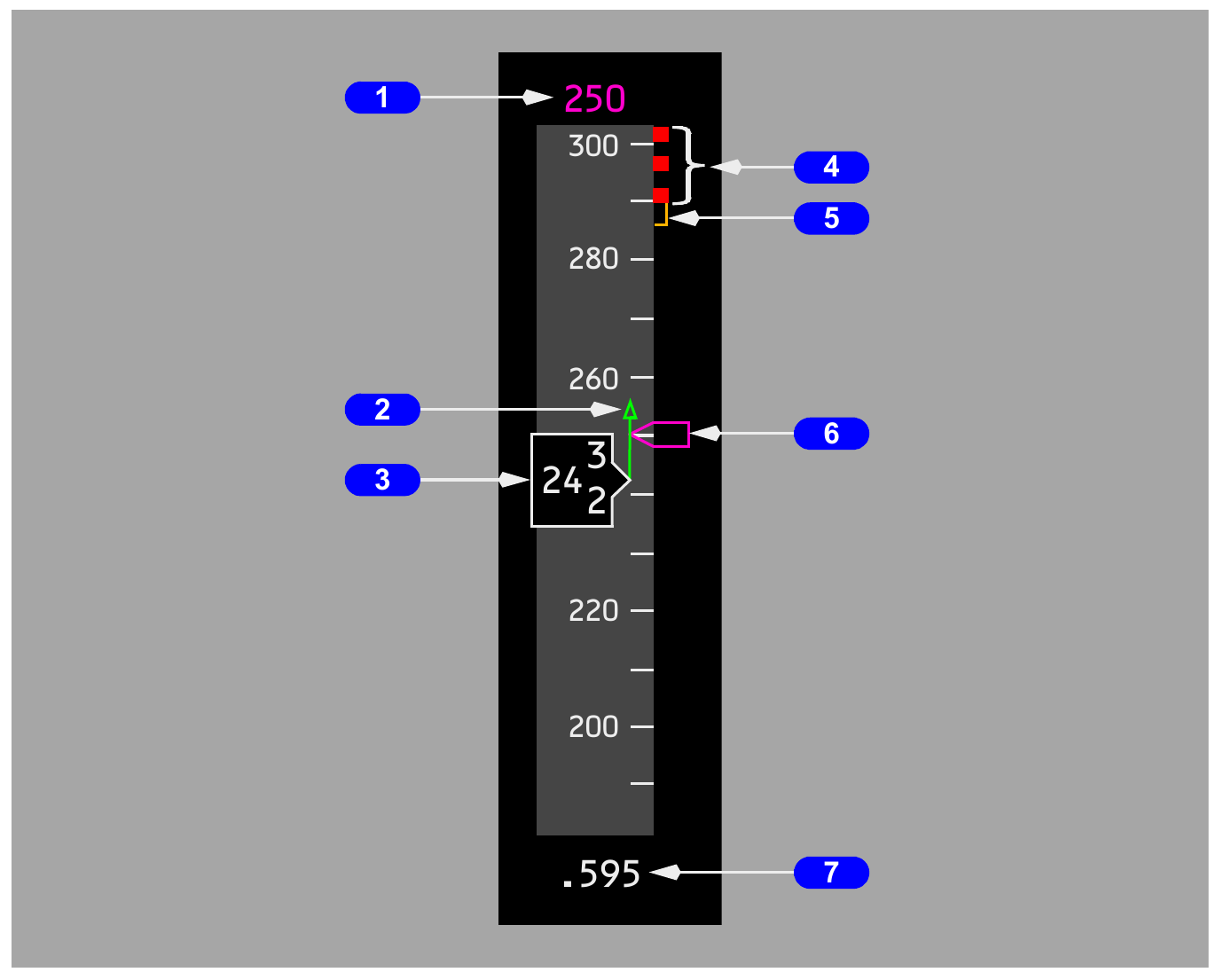
The airspeed tape combines current speed, the selected target, predicted trend, configuration limits and manoeuvre margins. It is not simply a digital airspeed indicator.
Current, selected and predicted speed
Current calibrated airspeed is shown in the central box once the indication becomes valid. The magenta bug and selected-speed value show the MCP target, or the FMC target when the IAS or Mach window is blank. If the target is beyond the visible tape, half of the bug remains parked at the appropriate edge.
The green trend vector projects the airspeed expected about ten seconds ahead from present acceleration. A long upward trend indicates rapid acceleration towards a higher speed; a downward vector warns that the aircraft is moving towards the lower margin.
Upper and lower margins
The red and black bar begins at the lowest applicable maximum, which may be Vmo or Mmo, the landing-gear placard limit or the flap placard limit. With flaps up, an amber upper band can show maximum manoeuvre speed or the high-speed buffet margin. The associated manoeuvre capability corresponds to approximately 1.3 g, which is about a 40 degree bank in level flight.
The amber lower band marks minimum manoeuvre speed. Below roughly 20,000 feet it is based on a margin to stick shaker. At higher altitude it is based on low-speed buffet or an approved alternative capability. Flying inside an amber band means reduced manoeuvre margin, even when a non-normal target requires it.
Takeoff, flap and approach references
Takeoff references include V1, VR and V2. A white V2 plus 15 bug can remain until flap retraction begins, or until a landing reference is entered. Once gross weight is available, green flap manoeuvre bugs identify the speed for each useful flap setting. These bugs are normally removed at flap 30 or 40 and may be inhibited close to VREF.
After a landing reference is entered, the display can show VREF and VREF plus 15. At higher altitudes the landing flap manoeuvre reference is suppressed because it is not operationally useful. Current Mach appears at or above Mach 0.40. Below that transition, the lower readout shows groundspeed; a temporary box identifies the change between the two presentations.
Attitude, steering and approach cues
The attitude area combines aircraft attitude with flight-director commands, flight-path information and approach deviation. The crew must distinguish aircraft motion from guidance commands.
Attitude and bank
The fixed aircraft symbol is read against the horizon and pitch scale. Bank marks cover zero through thirty degrees, with further references at forty-five and sixty degrees. The bank pointer and scale change to amber at 35 degrees or more. The slip and skid indication also becomes amber when bank is at least 35 degrees and the ball reaches full-scale displacement.
The amber pitch-limit indicator shows the pitch at which stick shaker would occur for existing conditions. It appears with flaps not up and can also appear at low speed with flaps up. It is a limit cue, not a command bar.
Flight director and flight path vector
Flight-director command bars direct the pitch and roll needed to satisfy the engaged modes. The pilot flies the aircraft symbol towards the bars, while continuously confirming the flight mode annunciations. The flight path vector, when selected, depicts actual flight-path angle vertically and drift laterally. Its vertical component depends on inertial and barometric altitude data, so unreliable primary altitude makes that vertical presentation unreliable.
Localizer, glideslope and IAN
A valid approach source brings the lateral pointer into view below the attitude sphere and the vertical pointer beside it. A pointer is solid magenta inside two and a half dots and becomes an outline at its limiting deflection. The localizer scale can expand during LOC operation when deviation is more than about half a dot and track remains within five degrees of the selected front course. The expanded scale is not used for an IAN final approach course.
Low-altitude excessive-deviation alerting changes the scale to amber and flashes the pointer. With LNAV engaged and the approach course armed but not captured, the localizer or final-approach-course alert is active below 1,000 feet AGL. Each side performs a brief deviation-alert self-test when the system arms at 1,500 feet radio altitude.
The rising-runway symbol appears below 2,500 feet radio altitude when usable lateral approach guidance is displayed. Below 200 feet it moves upward towards the aircraft symbol. It gives lateral orientation close to touchdown and does not replace the localizer pointer or outside visual references.
Altitude, minimums and vertical speed
The right side of the PFD joins barometric altitude, radio altitude, approach minimums and vertical speed. Each value has a different reference and therefore answers a different question.
Barometric altitude and setting
Current barometric altitude appears in the boxed window on the altitude tape. Selected altitude is shown above the tape and by a magenta bug. During acquisition, the current-altitude box becomes more prominent. An altitude-deviation condition highlights and flashes the indication.
The selected pressure reference appears below the tape in hectopascals or inches of mercury. A numeric setting carried above transition altitude, or standard pressure carried below transition level during descent, produces an amber box. A second setting can be prepared while standard pressure remains active.
BARO and RADIO minimums
| Selection | Reference | Display behaviour |
|---|---|---|
| BARO | Feet MSL | The selected minimum is tied to the barometric altitude scale and includes a pointer and reference line |
| RADIO | Feet AGL | The selected minimum uses radio height and is presented beside the attitude display |
| Below minimum | Selected source | The value changes to amber and flashes briefly |
| Reset | Go-around, touchdown or RST | The normal green state returns after the applicable reset condition |
On a go-around the minimums indication returns to green after climbing through the selected value plus about 75 feet. The landing-altitude reference bar is white from 1,000 to 500 feet above landing elevation and amber for the final 500 feet. A crosshatched landing-altitude area is taken from the FMC destination. Early in the flight it can represent the departure field until the aircraft is 400 NM from departure or halfway to destination, whichever point comes first.
Radio altitude and vertical speed
Radio altitude is displayed below 2,500 feet AGL and turns amber below a selected radio minimum. The exact visual form varies with the installed display standard, so crews must recognise their own aircraft presentation while applying the same threshold logic.
Vertical speed is shown by a pointer beside the altitude tape. A numeric value appears above the scale in a climb or below it in a descent when the magnitude exceeds 400 feet per minute. In MCP vertical-speed mode, a selected vertical-speed bug provides the commanded reference.
Navigation display modes and map information
The ND changes format to suit the task. MAP is the normal progress display, VOR and APP support raw-data work, and PLAN lets the crew inspect the programmed route from above.
The four basic modes
| Mode | Orientation | Use |
|---|---|---|
| MAP | Track up in the expanded presentation | Most phases of flight, with aircraft position shown against the active route |
| VOR | Heading up | VOR course, deviation and bearing information |
| APP | Heading up | Localizer or final approach course, glideslope or glide-path context |
| PLAN | True north up | Route review using the CDU LEGS page STEP prompt |
MAP, VOR and APP can use an expanded partial compass rose or a centred full rose. The map may include current track, selected and actual heading, groundspeed, true airspeed, wind, range scales, waypoint time and distance, range to selected altitude, weather radar, terrain and traffic. Optional overlays should be selected deliberately because too many symbols can hide the route picture.
Heading, track and range
Heading describes the direction the aircraft nose points. Track is the path over the ground. A track line projects forward from the aircraft symbol. Magnetic or true reference is annunciated, and a heading bug identifies the MCP selection. Range selection controls the map scale, while range arcs let the crew judge distance to weather, traffic or a descent constraint.
Position trend and route review
The position trend vector predicts where the aircraft will be in 30, 60 and 90 seconds if the present turn is maintained. At ranges greater than 20 NM it carries three segments. At 20 NM or less it has two, and at 10 NM or less it has one. This is a prediction tool, not a commanded path.
PLAN mode is particularly useful before departure and during arrival preparation. Stepping through each leg exposes discontinuities, wrong-side turns and route geometry that can be hard to detect on a small expanded map.
Vertical situation, terrain and traffic
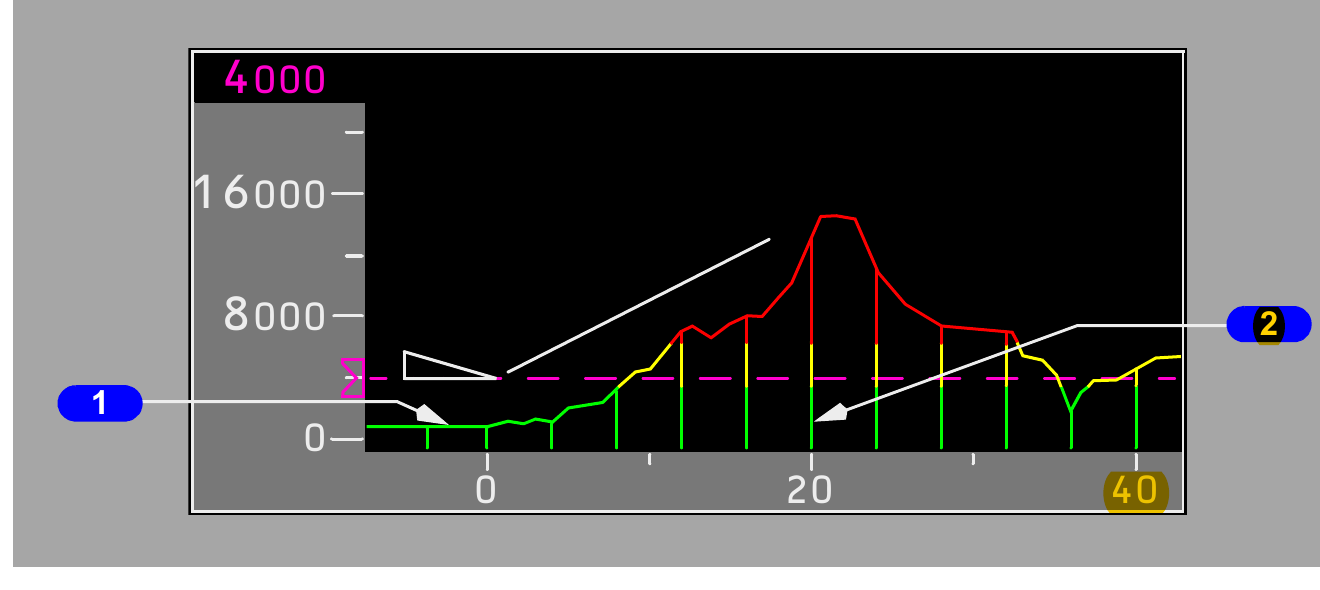
The vertical situation display converts the route ahead into a side view. It helps the crew understand terrain clearance, altitude constraints and the geometry of a descent, but it remains an awareness aid.
How the VSD is built
Cyan dashed lines on the ND define the enroute swath. The VSD profiles the highest terrain inside that corridor along the current track. The horizontal scale covers one half of the selected ND range. The aircraft symbol is positioned by present altitude, while vertical constraints, selected altitude and the projected path are placed against the terrain.
A white or magenta reference line can depict current flight path, selected vertical speed, the FMC approach angle or a three-degree reference anchored to the runway. Decision gates at 1,000 and 500 feet above field elevation support stabilised-approach awareness. They do not authorise descent below a published altitude.
Terrain colours
Green terrain is comfortably below the aircraft, generally more than 500 feet below, reduced to 250 feet with the landing gear down. Amber terrain lies from 500 feet below to 2,000 feet above the aircraft. Red identifies terrain more than 2,000 feet above. The terrain profile is drawn to preserve true altitude separation between the aircraft and terrain.
TCAS presentation
Traffic symbols can appear on the ND when traffic display is selected. Relative altitude and a trend arrow help describe the intruder. The arrow is shown for a vertical rate of at least 500 feet per minute; no arrow means the absolute vertical rate is below that threshold. Resolution-advisory guidance also appears on the PFD vertical-speed area so the pilot can fly the commanded vertical sense without chasing the traffic symbol.
Display sources, reversion and failure cues
Display reversion separates three failures that can look similar: a display unit can fail, a DEU can fail, or an EFIS control panel can fail. The annunciation and the automatic switching identify which layer is affected.
Display-unit failures
If a pilot's outboard display unit fails, that pilot's PFD transfers to the inboard unit and the failed unit blanks. The other pilot then cannot command that reassigned inboard display. If the upper centre unit fails, the engine display moves automatically to the lower unit. If secondary engine information was already there, a compact engine format preserves the essential indications.
A lower centre-unit failure has no automatic switching. The crew uses the display select controls and the non-normal procedure to recover the needed presentation.
DEU source failure
Failure of one DEU causes the remaining DEU to feed all six displays automatically. The amber DSPLY SOURCE 1 or DSPLY SOURCE 2 message identifies single-source operation on this configuration. The SOURCE selector is intended primarily for maintenance use on the ground and should normally remain in AUTO.
CDS FAULT is an amber, non-dispatchable common-display-system fault shown on the ground before the second engine is started. CDS MAINT is a white maintenance indication for a stored or adaptive fault and appears under the same ground condition. If flight-director information is affected by a DEU failure, the detailed response depends on altitude, phase of flight and which autopilot is engaged.
EFIS control-panel failure
The CONTROL PANEL selector normally stays at NORMAL, giving each pilot control from the respective EFIS panel. BOTH ON 1 lets the left panel control both sides. BOTH ON 2 does the same from the right. A control-panel failure annunciation directs the crew towards this reversion.
Air data and inertial reference
The air data inertial reference system, or ADIRS, supplies position, speed, altitude, attitude and related quantities to the displays and many other aircraft systems. It combines pneumatic air-data inputs with inertial sensing.
System elements
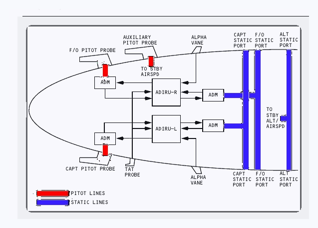
This aircraft has two ADIRUs, four air data modules, one inertial system display unit, one dual mode select unit, six static ports, three pitot probes, two alpha vanes and one total-air-temperature probe. The computed outputs serve cockpit displays, navigation and flight-management functions, control systems, engine systems and other users.
Air-data paths
Two main pitot probes and four main static ports feed air data modules. Each pitot module is connected only to its own side and has no cross-connection. The captain's pitot and static data feed the left ADIRU; the first officer's sources feed the right ADIRU. The modules convert pneumatic pressure into electrical signals before passing the values to the ADIRUs.
The standby instruments take ram pressure from the auxiliary probe and static pressure from the alternate ports. This physical separation is why disagreement between the two primary sides must be compared with standby data rather than automatically trusting the remaining primary display.
Disagree alerts
Airspeed and altitude disagree alerts compare the two primary indications for a sustained difference. The angle-of-attack disagree logic becomes active above 400 feet radio altitude and annunciates after the two computed values differ by more than ten degrees for longer than ten seconds. The flight crew responds with the applicable non-normal checklist and uses all reliable sources to decide which indication is credible.
Standby flight instruments
Standby instruments preserve essential attitude, airspeed, altitude and navigation references after loss or doubt of the primary displays. Their power and pressure sources are deliberately independent.
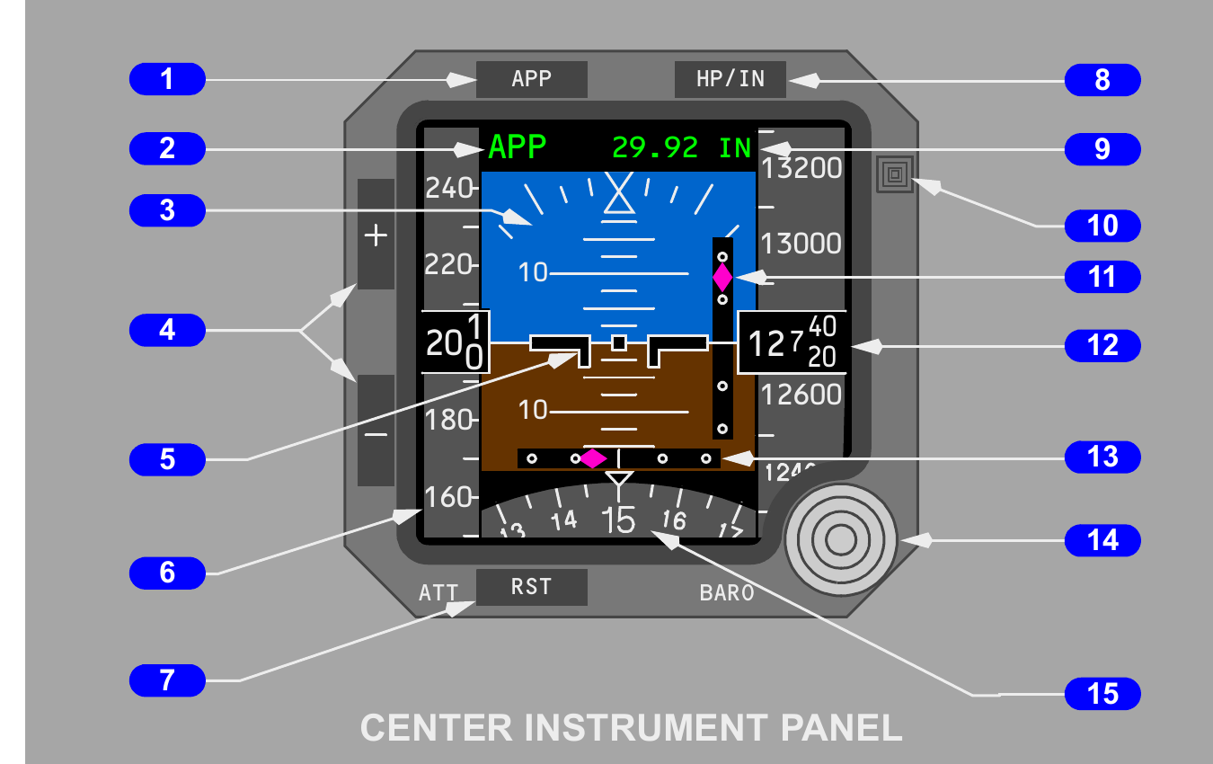
ISFD inputs and power
The integrated standby flight display presents attitude, airspeed, altitude, magnetic heading and localizer with glideslope deviation. Internal inertial sensors provide attitude. The auxiliary pitot and alternate static sources provide airspeed and altitude. Approach deviation comes from the number 1 multi-mode receiver, while heading comes from the number 1 ADIRU.
The battery bus powers the ISFD. Ten seconds after the battery switch is selected on, a 90-second initialisation begins. ATT and INIT 90s messages show during this period. Excessive aircraft movement pauses the alignment until motion becomes acceptable.
Attitude reset
An out-of-limit condition can blank the attitude presentation and show WAIT ATT or ATT:RST. On the ground, reset is performed with the aircraft stationary. In flight it requires wings level, non-accelerated flight. The instrument displays ATT 10s during the reset. If stable conditions are not maintained, the reset may fail and the instrument can remain unavailable.
Other standby references
The liquid-damped magnetic compass provides an independent magnetic heading reference. A correction card records installation error. The standby radio magnetic indicator shows magnetic heading and VOR or ADF bearing. Its AC standby supply continues after normal AC is lost, provided battery power remains available.
Clocks, flight recording and practical scan
Timekeeping and flight recording are quiet systems until accuracy, power or data capture matters. The same disciplined cross-check used on the PFD also applies to clocks and recorder status.
Electronic clocks
Two electronic clocks are installed. Each upper display shows time or date, and each lower display provides elapsed-time or chronograph functions. The clocks are compatible with GPS-derived coordinated universal time and can also be set manually. Standby 28 volt DC preserves the time base when normal power is absent, though the display and controls are not powered in that state.
Elapsed time supports sector and procedure timing. The chronograph provides short-interval timing. Crews should agree which function is in use, because starting or resetting one clock does not operate the other pilot's clock.
Digital flight data recorder
The solid-state recorder captures aircraft motion, position, system state, engine thrust and flight-control position against a time reference. It continuously preserves the latest 25 hours of operation by overwriting the oldest data. The crash-protected case is installed in the aft fuselage, includes an underwater locator beacon designed for about 30 days and can withstand water pressure associated with a depth of roughly 20,000 feet.
In flight, the recorder operates whenever electrical power is available. On the ground, normal operation additionally requires an engine to be running. The guarded test switch can power it for a ground check. An amber OFF light means the recorder is not operating or that the test result is invalid, which can result from a power, data-input or internal fault.
Aircraft condition monitoring
The aircraft condition monitoring system gathers selected engine and aircraft performance information for maintenance and operational analysis. Stored or real-time data can be presented on the control display unit and can support reports sent through the aircraft communication system.
A practical instrument scan
- Confirm the flight mode annunciations and selected targets.
- Cross-check attitude, airspeed, altitude and vertical speed for a coherent aircraft response.
- Use the ND for route, weather, traffic and terrain context.
- When information disagrees, compare both primary sides with the independent standby source.
- Identify the failed layer before changing a display source or control-panel selection.