
Flight-deck window heat and rain protection
Electrical window heat keeps the principal flight-deck panes clear and brings them to the strength intended for bird impact. Windscreen air and wipers provide separate help with fogging and rain.
Which windows are heated
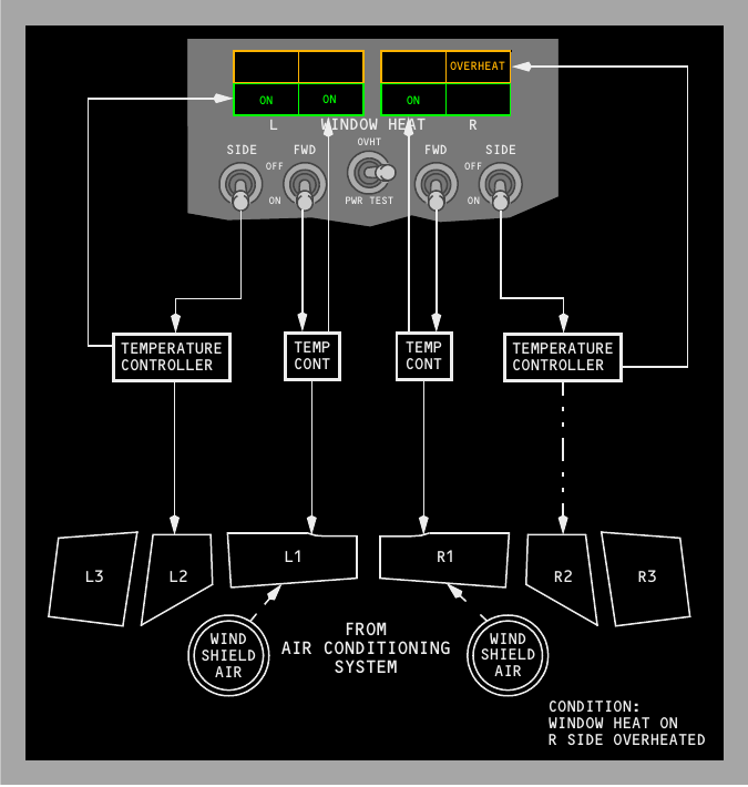
Each No. 1 and No. 2 window has glass laminates around a vinyl core. A conductive film on the outer glass receives electrical power to resist icing and fogging. Each No. 3 window uses two acrylic panes with an air gap and is not electrically heated on this configuration.
The FWD WINDOW HEAT switches serve the No. 1 panes. The SIDE WINDOW HEAT switches serve the No. 2 panes. Temperature controllers regulate both pairs. Their controlled heating also conditions the glass for its designed impact strength. An overheat causes automatic removal of electrical power from the affected No. 1 or No. 2 pane.
| Panel item | Indication or action |
|---|---|
| Green ON light illuminated | Electrical heating is being delivered to the selected pane. |
| Green ON light extinguished | The switch can be OFF, the correct temperature may have been reached, or an overheat or system fault may be present. |
| Amber OVERHEAT light | An overtemperature is detected. The same light can also illuminate if the pane loses electrical power. |
| OVHT test | Checks the overheat response by creating a simulated hot condition. |
| PWR TEST | Runs a confidence check of window-heat operation. |
Windscreen air and wipers
Pulling either WINDSHIELD AIR control directs conditioned air towards its No. 1 pane for defogging. The nearby FOOT AIR control supplies the pilot's leg area. Each wiper selector has PARK, INT, LOW and HIGH. INT produces one sweep cycle about every seven seconds, while PARK stops the motor and returns the blade to its stowed position.
A permanent rain-repellent surface treatment complements the wipers. There is no separate liquid-repellent selection in this system description. Wipers must not be run on a dry windscreen because the blade action can scratch it.
Probe and sensor heat
Air-data and angle-of-attack sensors need reliable heating because ice at a sensing surface can corrupt the information used by instruments and warning systems.
Heated and unheated sensing points
Electrical heat is installed at the Captain, First Officer, auxiliary and elevator pitot probes. It also protects the temperature sensor and both alpha vanes. The static ports are not heated. Individual amber panel lights identify a related probe or vane that is not receiving effective heat during normal powered operation.
The A and B PROBE HEAT switches divide the sensing elements between two channels. ON supplies the associated channel directly. In AUTO, both channels receive heat automatically once either engine is running. This removes reliance on a separate manual selection after engine start while preserving an explicit ON selection.
Standby-power behaviour
On standby electrical power, only the Captain's pitot probe remains heated. The Captain's pitot warning light does not then provide a trustworthy failure indication, and the standby-airspeed pitot source has no heat in that condition. The general amber-light rule therefore cannot be applied unchanged during standby-power operation.
The total-air-temperature probe is normally heated in flight as part of the sensor system. A TAT TEST switch, where fitted to the panel variant, energises the temperature probe on the ground for its prescribed test.
| Item | Normal heating | Standby-power note |
|---|---|---|
| Pitot probes | Electrically heated | Captain's pitot only remains heated. |
| Total-air-temperature probe | Electrically heated | Not part of the reduced standby heating supply. |
| Alpha vanes | Electrically heated | Not part of the reduced standby heating supply. |
| Static ports | Not heated | No change. |
| Standby-airspeed pitot source | Heated with the normal system | Not heated on standby power. |
Engine thermal anti-ice
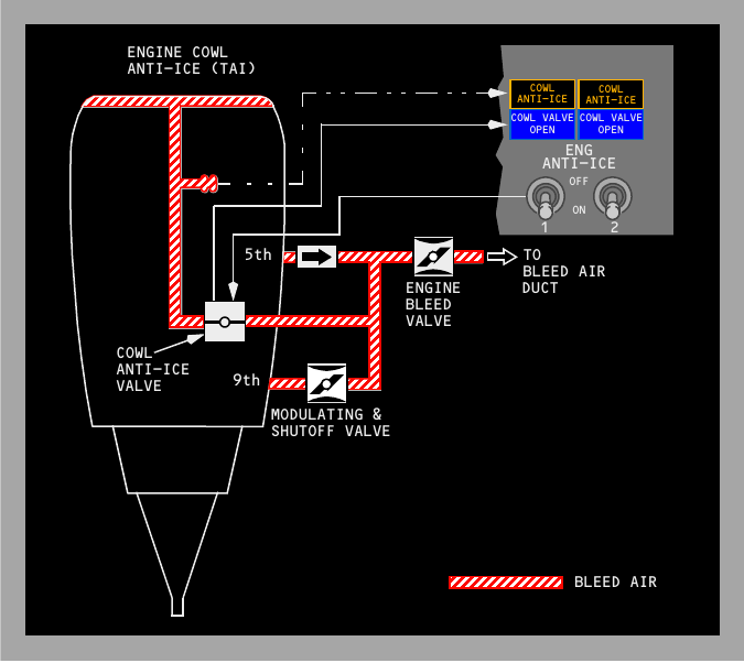
Each engine uses its own bleed-air supply to warm the cowl lip. The flight crew can use engine anti-ice on the ground or in flight, and each side has independent valve monitoring.
Air path and valve operation
Selecting an ENG ANTI-ICE switch ON electrically commands its pressure-operated cowl valve. Hot bleed air then passes into the cowl-lip duct and is later discharged. Because the system consumes compressor air, its operating effects connect directly to engine performance and pneumatic-system awareness.
The selection also changes stall-warning calculations for icing. Stick-shaker scheduling and the minimum-manoeuvre-speed bars on the airspeed display are adjusted, but the VREF presented by the flight-management computer is not changed automatically.
Indications and protection
| Indication | What it tells the crew |
|---|---|
| Blue COWL VALVE OPEN, dim | The related valve is open with its switch selected ON. |
| Blue COWL VALVE OPEN, bright | The valve is travelling or its sensed position disagrees with the switch. |
| Green TAI on the engine display | The valve is open and the corresponding engine anti-ice switch is ON. |
| Amber TAI | The cowl valve does not match the commanded position after a brief validation delay. |
| Amber COWL ANTI-ICE | Pressure is excessive in the duct downstream of the cowl valve. |
With both engine anti-ice switches OFF, normal stall-warning logic returns only if wing anti-ice has not already been used during the flight. Once wing anti-ice has been selected airborne, the icing bias follows a separate remainder-of-flight rule explained on the next page.
Wing thermal anti-ice
Wing anti-ice directs bleed air to selected leading-edge surfaces. Its ground logic protects the ducts and takeoff thrust, while its airborne logic prioritises continuous valve command.
Heated surfaces and hardware
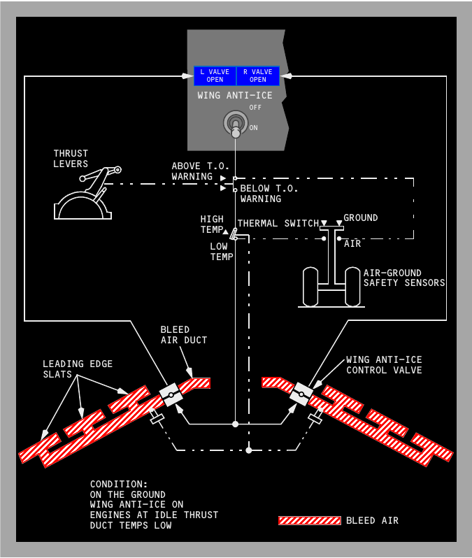
Each wing supplies its three inboard leading-edge slats. The outboard leading-edge slats and the leading-edge flaps are not heated by this system. An AC motor drives each wing anti-ice control valve. When open, the valve sends bleed air along the heated slats, after which the air vents overboard. Protection is available at every slat position.
Ground operation
With WING ANTI-ICE selected ON on the ground, both valves can open only while both engines remain below the takeoff-warning thrust setting and both duct-temperature switches remain cool. Either engine reaching the takeoff-warning setting closes both valves. An overtemperature sensed in either wing duct also closes both. The switch itself stays ON, so the valves can reopen automatically after both thrust levers are reduced and both ducts cool.
At lift-off, changing to the air mode causes the WING ANTI-ICE switch to trip to OFF. That action prevents an unnoticed ground selection from carrying into airborne operation.
Airborne operation
Selecting WING ANTI-ICE ON in flight commands both valves open. Ground thrust and duct-temperature interlocks no longer influence them. The blue VALVE OPEN lights are dim when the valves agree in the open position, bright while travelling or disagreeing, and extinguished when closed.
An airborne wing anti-ice selection sets the stall-warning system for icing and keeps that bias for the rest of the flight, even if the switch is later turned OFF. Stick-shaker and minimum-manoeuvre-speed indications reflect the icing schedule; flight-management-computer VREF still requires the applicable crew action rather than an automatic anti-ice correction.