
Controls, indications and hydraulic architecture
Three independent fluid circuits provide hydraulic power: system A, system B and standby. The two main systems share the primary flight-control workload, while each also supplies a different collection of secondary services. The standby circuit protects a smaller set of critical functions.
The three-system design
Either main system can operate all primary flight controls without reducing controllability. That redundancy does not make the secondary users identical. System A and system B each have their own reservoir, engine-driven pump and AC electric pump. A third reservoir and one electric pump form the standby system.
All reservoirs are in the main-wheel-well area. Bleed air pressurises the A and B reservoirs so fluid reaches their pumps positively. The standby reservoir receives its pressurisation and servicing connection through the system B reservoir.
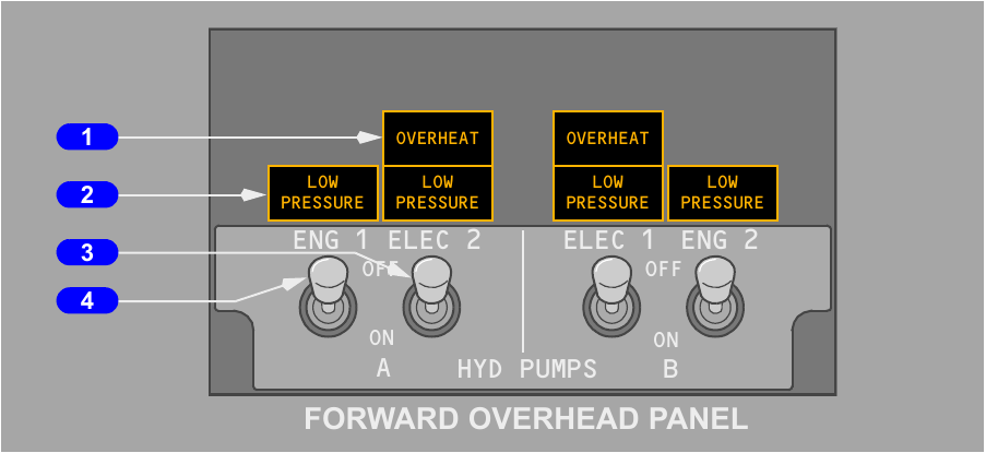
Pump controls and lights
| Control or light | Meaning | Operational detail |
|---|---|---|
| Engine pump switch ON | The blocking valve is not energised, so pump discharge enters its system. | It normally remains ON during shutdown to reduce solenoid duty. |
| Engine pump switch OFF | The blocking valve is energised and isolates pump output from the system. | The mechanically driven pump still turns while its engine runs. |
| Electric pump switch ON | Electrical power is supplied to the selected AC motor-driven pump. | Switching OFF removes electrical power from that pump. |
| LOW PRESSURE | The related pump is not producing adequate discharge pressure. | Pulling the associated engine fire switch suppresses that engine pump's light. |
| OVERHEAT | The electric pump or its cooling and lubricating fluid has overheated. | On this configuration the light gives the warning; it does not by itself remove pump power. |
Flight-control and standby indications
Each FLIGHT CONTROL switch is guarded ON for normal operation. OFF shuts the related flight-control valve and separates that main system from the ailerons, elevators and rudder. STBY RUD starts the standby pump, isolates the selected main source from those controls and opens the standby rudder valve.
A flight-control LOW PRESSURE light reports inadequate A or B pressure to the primary controls. It is inhibited after the same FLIGHT CONTROL switch is placed to STBY RUD and the standby rudder valve opens. The standby LOW QUANTITY light is continuously armed. The standby LOW PRESSURE light becomes active only when standby operation has been selected or commanded automatically. STBY RUD ON confirms a command to pressurise the standby rudder actuator.
System A and system B distribution
System A and system B meet at the primary flight controls but divide the remaining work. Remembering that division explains why a single-system loss affects some services directly while leaving others on their normal source.
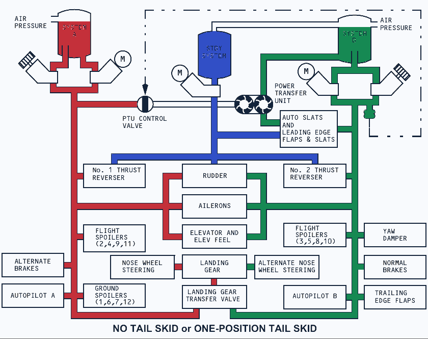
Who powers what
| System A users | System B users | Both main systems |
|---|---|---|
| Ground spoilers | Leading-edge flaps and slats | Ailerons |
| Alternate brakes | Trailing-edge flaps | Rudder |
| Number 1 thrust reverser | Normal brakes | Elevator and elevator feel |
| Autopilot A | Number 2 thrust reverser | Flight spoilers, with separate panels assigned to A and B |
| Nose-wheel steering in its normal mode | Autopilot B | |
| Landing gear and PTU driving pressure | Alternate nose-wheel steering, autoslats and yaw damper | |
| Alternate pressure for landing gear and its transfer valve |
Pump sources and capacity
Engine 1 drives the system A engine pump and engine 2 drives the system B engine pump. The electric pumps are cross-numbered on the panel: ELEC 2 belongs to A and ELEC 1 belongs to B. Each engine-driven pump can move roughly six times as much fluid as its companion electric pump.
If one engine pump is lost during a period of high demand, the remaining electric pump may briefly show LOW PRESSURE. That pressure condition can also bring on the matching flight-control light, MASTER CAUTION, FLT CONT and HYD annunciations.
Cooling, isolation and pressure indication
Return fluid used to cool and lubricate the pumps passes through a fuel-cooled heat exchanger. The system A exchanger is in main fuel tank 1 and the system B exchanger is in main tank 2. Ground use of an electric hydraulic pump requires at least 760 kg of fuel in its related main tank.
A pressure switch monitors each pump outlet. A check valve prevents one pump from back-feeding through the other, and the system pressure transmitter measures their combined contribution for the flight-deck indication.
Quantity and pressure displays
Selecting SYS on the multifunction display control presents hydraulic quantity and pressure. Quantity is shown digitally from 0 to 106 percent. Normal system pressure is 3000 psi and the upper published pressure is 3500 psi. With both pumps of one system OFF, the display can settle near reservoir pressure, usually below 100 psi.
RF appears below 76 percent quantity. Its refill meaning is valid on the ground when both engines are shut down, or during taxi after landing with the flaps retracted. Reservoir-mounted indications provide another quantity reference.
Leaks, the PTU and landing-gear transfer
The reservoirs and transfer devices are designed around specific failures. A standpipe can preserve fluid for one source, the PTU can exchange mechanical power without mixing fluid, and the landing-gear transfer valve can bring system B volume to the gear.
System A leak signatures
The system A reservoir feeds its engine pump through a standpipe. A leak in that engine-pump branch lowers indicated quantity to about 20 percent, then leaves fluid for the electric pump. System pressure can therefore remain available from the electric source.
A leak in the electric-pump branch, or in plumbing shared by both pumps, has a different signature. Quantity continues towards zero and the system ultimately loses pressure because the preserved standpipe supply cannot isolate that leak path.
System B leak signature
System B uses one standpipe for both of its pumps. A leak in a B pump, line or common component therefore drives the indicated quantity towards zero and removes B pressure. Fluid held below the standpipe remains available to the PTU circuit. The separate standby system is not lost merely because system B has leaked away.
| Leak location | Quantity trend | Pressure outcome |
|---|---|---|
| System A engine-pump branch | Stops near 20 percent | Electric pump can retain A pressure |
| System A electric branch or common section | Falls towards zero | System A pressure is eventually lost |
| System B pump, line or common section | Falls towards zero | System B pressure is lost, but PTU reserve remains below the standpipe |
Power transfer unit
The PTU uses system A pressure to turn a hydraulic motor. That motor drives a pump which raises pressure in system B fluid. The two fluid systems stay separate, so the unit transfers power rather than transferring hydraulic fluid.
Automatic PTU operation requires low pressure from the system B engine-driven pump, an airborne aircraft and a flap position below 15 but not fully retracted. Its extra flow lets the autoslats and leading-edge devices operate at their normal rate when the B engine pump cannot provide the required volume.
Landing-gear transfer valve
This valve brings system B engine-pump volume to the landing-gear circuit when the system A engine pump cannot raise the gear at the normal rate. It operates with the aircraft airborne, engine 1 RPM below its trigger, the gear lever UP and at least one main gear not yet up and locked.
The PTU and the landing-gear transfer valve solve different problems. The PTU uses A pressure to boost B-side flow for leading-edge devices. The gear transfer function uses B engine-pump flow to support a normally A-powered landing-gear retraction.
Standby operation and quantity behaviour
The standby electric pump supplies the rudder, both thrust reversers, extension of the leading-edge devices and the standby yaw damper. It can be commanded by the crew or started automatically by the aircraft's monitoring logic.
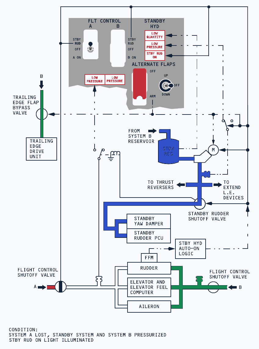
Manual selection with STBY RUD
Moving either FLIGHT CONTROL switch to STBY RUD starts the standby electric pump. The related main-system valve closes, isolating that source from the ailerons, elevators and rudder, while the standby rudder valve opens. The associated flight-control LOW PRESSURE light is then suppressed.
The standby system becomes available to the rudder and thrust reversers. STBY RUD ON, MASTER CAUTION and the FLT CONT annunciation accompany this commanded state.
Manual selection with alternate flaps
ARM on the ALTERNATE FLAPS master switch also starts the standby pump. It closes the trailing-edge flap bypass valve and arms the alternate-flap position control. Standby pressure can then extend the leading-edge flaps and slats and remains available to the thrust reversers. Standby pressure does not retract the leading-edge devices.
Automatic standby activation
The automatic path starts after a loss of main-system A or B when the flaps are extended, the applicable FLIGHT CONTROL switch is ON, and the aircraft is airborne or wheel speed is above 60 knots. A trip of the main rudder power-control-unit Force Fight Monitor is an independent automatic trigger.
Automatic activation starts the electric pump and opens the standby rudder valve. The standby system then supplies the rudder and thrust reversers, while STBY RUD ON, MASTER CAUTION and FLT CONT alert the crew.
| Selection or trigger | Standby effect | Important limit of use |
|---|---|---|
| Either FLIGHT CONTROL switch to STBY RUD | Pump runs and standby rudder valve opens | Related main pressure is isolated from aileron, elevator and rudder |
| ALTERNATE FLAPS to ARM | Pump runs and alternate flap control is armed | Leading-edge devices receive extension pressure only |
| Main system loss with flap and speed or airborne logic satisfied | Automatic rudder backup | The matching flight-control switch must be ON |
| Main rudder Force Fight Monitor trip | Automatic rudder backup | Independent trigger path |
Leak and normal quantity changes
A standby-system leak empties the standby reservoir. LOW QUANTITY illuminates at roughly half reservoir quantity. System B continues to function, although its displayed reservoir level falls and then settles near 70 percent because of the connection used to pressurise and service standby.
Hydraulic quantity normally moves when a system is pressurised after engine start, when the gear or leading-edge devices travel, and after cold soaking during a long cruise. These changes are expected and have little operating effect.
Inadequate reservoir pressurisation at altitude can aerate the fluid. Pressure then fluctuates, pump LOW PRESSURE lights may blink, and MASTER CAUTION with the HYD annunciator can appear briefly.