
Dimensions and ground geometry
This lesson describes a 737-800 fitted with winglets. Where the manual divides the fleet by model or registration, the figures below are the ones for that winglet configuration.
Principal dimensions
| Dimension | Imperial | Metric |
|---|---|---|
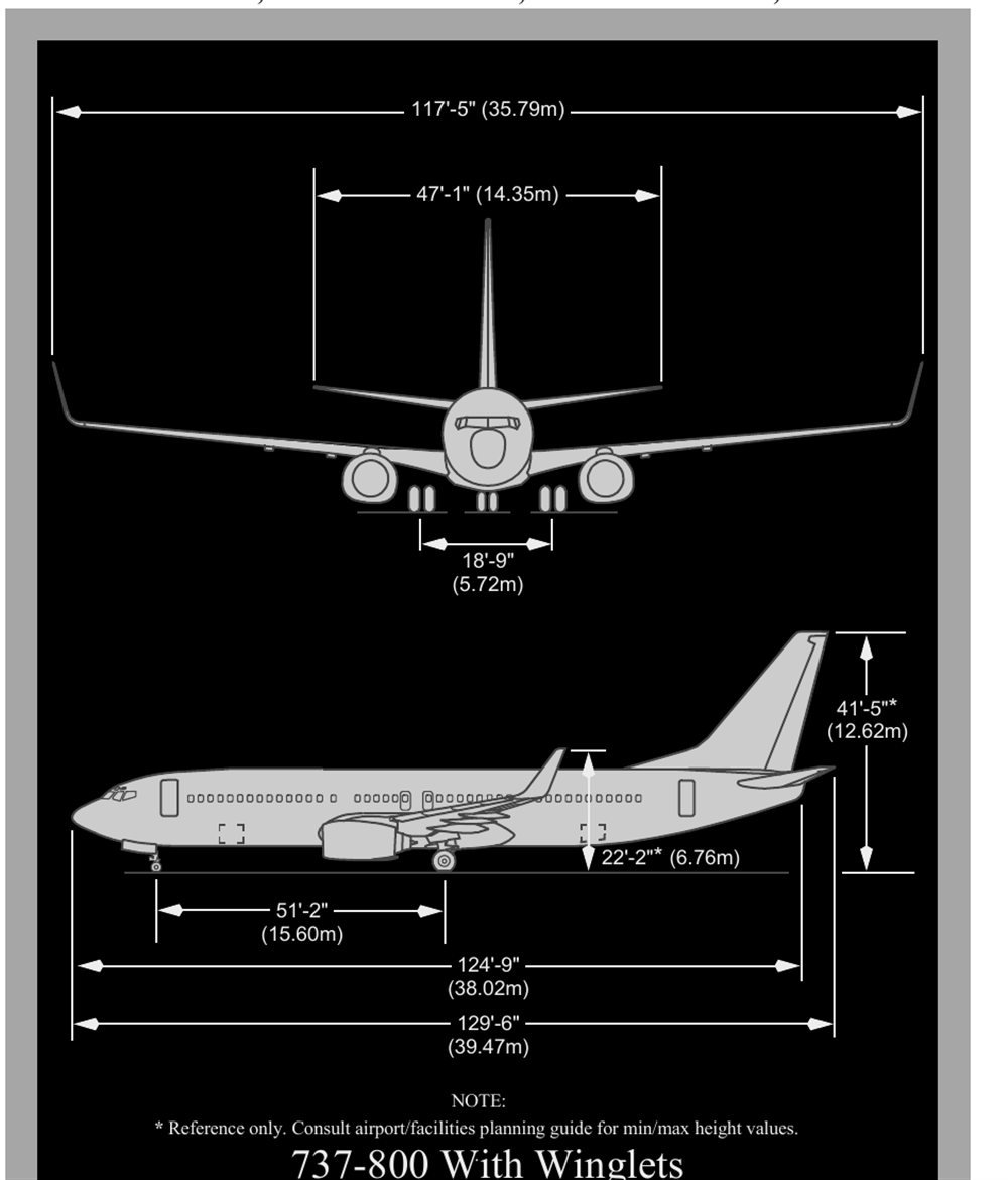
| Overall length | 129 ft 6 in | 39.47 m |
| Wingspan | 117 ft 5 in | 35.79 m |
| Overall height, reference figure | 41 ft 5 in | 12.62 m |
| Horizontal-tail span | 47 ft 1 in | 14.35 m |
| Main-gear track | 18 ft 9 in | 5.72 m |
| Wheelbase | 51 ft 2 in | 15.60 m |
The height value is a planning reference. Airport compatibility work uses the applicable facilities-planning data for minimum and maximum heights.
Minimum-radius turn
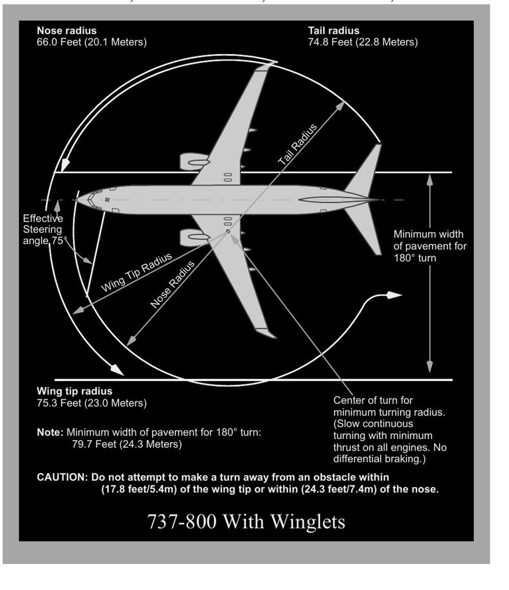
At an effective steering angle of 75 degrees, the wingtip traces the widest structural arc. Its radius is 75.3 ft or 23.0 m. Nose radius is 66.0 ft or 20.1 m, while tail radius is 74.8 ft or 22.8 m. A 180-degree turn needs at least 79.7 ft or 24.3 m of pavement in the stated slow, minimum-thrust, no-differential-braking condition.
Do not turn away from an obstacle lying within 17.8 ft or 5.4 m of the wingtip, or within 24.3 ft or 7.4 m of the nose.
Flight-deck layout and lighting controls
The chapter begins with a map of the flight deck, then introduces controls whose logic is easier to understand before studying their individual systems.
Panel map
The crew works across the forward and aft overhead panels, glareshield, left and right forward panels, centre instrument panel, Captain and First Officer side panels, forward and aft electronic panels, and the control stand. The illustrations are representative; the system chapters remain the authority for the installed control and indication.
| Area | Primary role |
|---|---|
| Forward panels and centre instrument panel | Primary flight, engine and central system indications |
| Glareshield | Mode-control and warning area immediately above the displays |
| Forward overhead | Major aircraft-system controls and exterior-light switching |
| Aft overhead | Additional system controls, dome light and ELT area |
| Forward and aft electronic panels | FMS entry, communication and selected door controls |
| Control stand | Thrust, flap, speed-brake, trim and related controls |
Flight-deck illumination
Dome lighting provides general flood illumination. The glareshield supplies background lighting, and instruments and panels have integral lighting. Map, chart and utility lights have local controls at the pilot stations. If normal electrical supply is lost, standby power supports selected essential illumination, including the standby compass light and dome or flood lighting needed to interpret critical indications.
Master lights test and dimming
TEST drives the applicable overhead and selected pilot-panel system lights to full brilliance. BRT selects the bright level, while DIM reduces them. Selecting TEST also recalls the master-caution system. After the switch is released, a stored fault leaves its associated annunciation lit.
Landing and taxi-light switching
RETRACT stows and extinguishes the retractable landing lights. EXTEND places them in the airflow without illumination, while ON both extends and lights them. The fixed landing and runway-turnoff lights use ordinary OFF and ON selections.
This aircraft has the AUTO taxi-light version. Its light is carried on the nose gear and is extinguished automatically when that gear retracts. Some aircraft in the fleet carry a different taxi-light version — check your own tail number's configuration.
Cabin signs, emergency lighting and ELT
Normal lighting guides passengers and crew; emergency lighting preserves an evacuation path after a power change. The ELT then provides a distinct post-accident alerting function.
Exterior-light groups
The aircraft has retractable and fixed landing lights, runway-turnoff lights, a nose-gear taxi light, logo lights, position lights, white strobes, upper and lower red anti-collision lights, wing-illumination lights and wheel-well lights. For the winglet configuration, red and green position lights sit at the left and right winglet bases, with white lights aft; the winglets and tail cone carry the white strobes.
Passenger signs
In AUTO, FASTEN BELTS and RETURN TO SEAT illuminate if either the flaps or landing gear are extended. They go out only when both systems are retracted. Manual OFF and ON control remains available. The no-smoking indication is permanently configured to show that smoking is prohibited; moving its switch to ON produces a low cabin chime.
Emergency exit lights
| Selector or condition | Result |
|---|---|
| OFF | Prevents automatic emergency-light operation after aircraft power is lost or removed |
| ARMED | Lights remain ready and automatically illuminate if DC bus No. 1 supply fails or AC power is switched off |
| ON | All emergency lights illuminate |
| Aft-attendant guarded switch ON | Overrides flight-deck control and commands emergency lighting |
Exit signs, aisle guidance, floor-proximity markings, door-area lighting, exterior emergency lights and slide lighting make the approved evacuation routes visible. A separately powered bulb in the aft dome light supports flight-deck evacuation.
Emergency locator transmitter
On this configuration, an amber ELT light means that the beacon is active. It broadcasts the emergency sweep on 121.5 MHz and 243.0 MHz, while 406.0 MHz carries the alert with encoded position data. ARM permits automatic activation at the preset acceleration threshold; ON starts transmission manually. Reset begins in ARM, uses ON for 1 second, then returns to ARM.
Crew, passenger and portable oxygen
Crew and passenger oxygen are independent. This configuration uses a single crew cylinder with automatic pressure-breathing masks, while the cabin uses separate chemical sources at individual service units.
Flight-crew oxygen
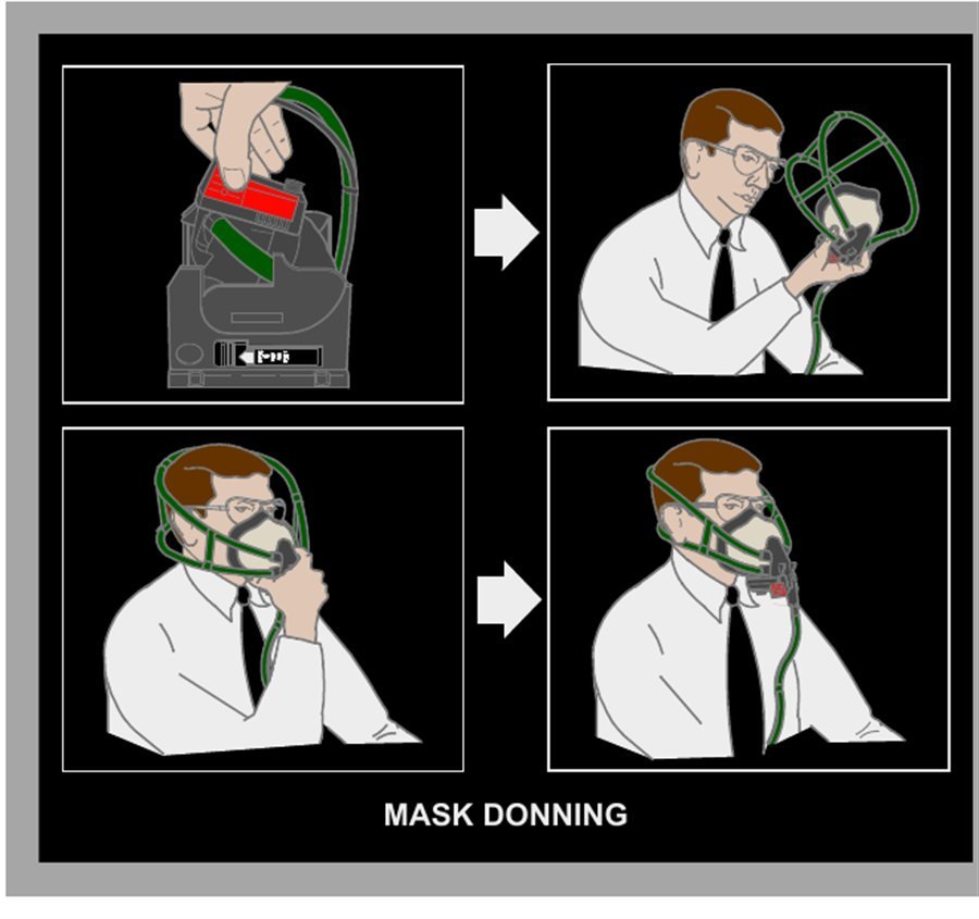
Quick-donning masks are provided at the crew stations. A single cylinder supplies them through pressure reduction, and the indicated system pressure can reach 1,850 psi. Automatic pressure breathing begins above 27,000 ft.
With NORMAL selected, the regulator delivers an air and oxygen mixture on demand. The 100 percent position supplies pure oxygen on demand. EMERGENCY gives pure oxygen at slight positive pressure, helping prevent smoke or harmful vapour from entering the mask. The emergency mode consumes oxygen more rapidly and can make speech less clear.
Passenger oxygen
Each passenger service unit has its own oxygen source connected to four continuous-flow masks. Two-mask sources serve each attendant station and lavatory. A pressure switch deploys the system at 14,000 ft cabin altitude, or the aft-overhead PASSENGER OXYGEN switch can be moved to ON.
Pulling any mask from one unit initiates its source, releases every mask in that unit and starts pure-oxygen flow to all of them. A green indicator in the hose confirms flow. On this configuration, supply lasts about 12 minutes and cannot be stopped after initiation. A compartment that does not open automatically can be released manually.
Portable oxygen and PBE
The portable cylinder in this configuration is charged to 1,800 psi and contains 11 cubic ft or 311 litres of free oxygen at the stated reference condition. One outlet gives 2 litres per minute for walk-around use; the other provides 4 litres per minute for first aid. Capacity is another figure that can vary by aircraft — check your own tail number's data.
Protective breathing equipment may be stowed around the cabin for crew firefighting or entry into smoke and fume areas. Depending on the device, usable oxygen is approximately 15 to more than 20 minutes. The container carries its own operating directions.
Fire extinguishers and emergency equipment
The extinguishing agent must suit the material burning. Crew protection continues after discharge because agent concentration and fire by-products can remain hazardous.
Water and chemical extinguishers
| Fire material | Suitable portable agent | Key caution |
|---|---|---|
| Paper, fabric, wood and similar ordinary combustibles | Water extinguisher | Avoid water on grease or live electrical equipment |
| Flammable liquids and grease | Halon or equivalent chemical agent | Use the installed placard and fire-class guidance |
| Live electrical equipment | Halon or an equivalent non-conducting agent | De-energise the equipment first when practicable |
A water bottle is removed, armed by rotating its handle fully clockwise, aimed at the base of the fire and discharged with the trigger. Its water and antifreeze solution is intended for ordinary combustible material.
Protection after a chemical-agent discharge
Before discharging Halon or an equivalent bottle on the flight deck, every flight-deck crewmember wears an oxygen mask with 100 percent and EMERGENCY selected. The concentrated agent and heated by-products are toxic. Following a full-bottle discharge, allow for dissipation that can require as long as 7 minutes, and keep respiratory protection on until smoke and agent have cleared.
Emergency-equipment stowage
The chapter uses location diagrams and standard symbols to identify installed survival, medical, firefighting and communication equipment. Exact stowage is checked against the aircraft-specific diagram and placards during preparation; a generic drawing must not replace the physical location check.
Doors and flight-deck access
This access layout includes a pair of passenger entry doors and a pair of service doors. It also provides one flight-deck door, two lower-cargo doors, and underside access panels for the electronic and equipment spaces.
Wind limits for entry and service doors
Do not operate an entry or service door when wind at the door is above 40 kt. A door must not be left open when gusts exceed 65 kt, because the structure can be damaged.
Flight-deck door
The inward-opening door provides resistance to forced entry and ballistic penetration. With electrical power available it locks when closed; loss of that power releases the electrical lock. A viewing lens allows the cabin side to be observed, and a deadbolt arrangement can either permit or prevent use of the cabin-side key.
The access system comprises the cabin keypad and status lights, a chime, the AUTO, UNLKD and DENY selector, LOCK FAIL and AUTO UNLK indications, and the access-system switch. Moving the access-system switch to OFF removes lock power.
| Indication or selection | Meaning |
|---|---|
| Red keypad light | Door locked, or the access-system switch is OFF |
| Amber keypad light | Correct emergency code entered |
| Green keypad light | Door unlocked |
| LOCK FAIL | AUTO selected with lock failure, or access-system switch OFF |
| AUTO UNLK | Valid emergency code accepted; it flashes with a continuous chime before timed unlocking |
| UNLKD | Unlocks the door while held |
| DENY | Rejects the entry request and blocks another keypad attempt for a period |
Decompression panels
Two pressure sensors release the decompression panels if pressurisation is lost. Manual pins provide an alternate release so the panels can form an egress opening when the door itself is jammed.
Windows, cargo compartments and escape
The opening flight-deck windows, pressure-compartment features and exit routes work together to provide access, pressure relief and evacuation capability.
Number two flight-deck windows
Each No. 2 window is operable during flight as well as while parked, and either one can provide an emergency escape route. The trigger and handle first move the window inward, after which it slides aft and locks open. Closing begins by releasing it with the latch rod, moving it forward, then turning the handle forward and outboard without lifting it. From outside, only the First Officer's No. 2 window can be opened.
Lower-cargo compartments
The forward and aft holds are Class C compartments. They are sealed and pressurised so a fire is contained, but unlike the passenger cabin they do not receive normal fresh-air circulation or temperature control. Their right-side doors are inward-opening pressure plugs, upper-hinged and manually operable from either side.
A pressure-equalisation valve keeps each hold close to cabin pressure during normal changes. Blowout panels provide a much larger relief path if aircraft pressurisation is lost. The manual prints a sliding-carpet warning for some registration groups only; it isn't included here because it doesn't apply to this configuration, which is one more reason to check what applies to your own tail number.
Evacuation routes and straps
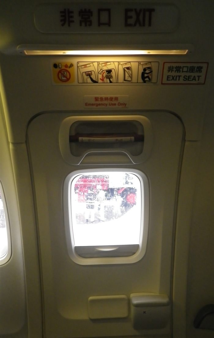
On this configuration, evacuation is available through four entry or service doors and four overwing hatches; flight-deck crew also have the two sliding windows. Flight-deck escape straps support descent from the window openings. Aft-door-frame straps can be attached to a wing fitting to provide a handhold during ditching evacuation towards a raft.
Overwing flight locks and cabin-service systems
The overwing exits use electrical logic to stay secured during flight yet release on the ground or after loss of DC power. The remaining general systems support crew position and cabin service.
Overwing exits and 28-volt DC locking
Four Type III canopy-style exits sit above the wings. A spring-loaded handle permits opening from either side. The electrical flight lock uses engine speed, thrust-lever position, air or ground state, and door position to decide when the exit must be secured.
The lock command requires at least three of the four entry or service doors closed, either engine running, and either an airborne indication or both thrust levers advanced. If any one of those conditions disappears, or DC supply is lost, the overwing exits unlock.
During the takeoff roll or in flight, an incompletely closed exit or a lock that is not engaged produces the left or right overwing warning, the DOORS annunciator and MASTER CAUTION. A flight-lock fault can also illuminate PSEU, OVERHEAD and MASTER CAUTION. That fault set is inhibited from takeoff until 30 seconds after ground mode is regained.
Flight-deck seats
This configuration has adjustable Captain and First Officer seats plus first and second observer seats. Pilot-seat controls set height, thigh support, recline, armrest, lumbar support and headrest. Correct adjustment places the eyes at the defined glareshield and display sight references. The first observer seat folds into the sidewall; its lower cushion is certified for flotation. The second observer seat is fixed behind the Captain.
Galleys and potable water
Galley equipment uses 115-volt AC from the transfer buses. Pressurised potable water supplies the galleys and lavatory basins, and can be isolated locally. One water tank is installed aft of the rear cargo compartment. A quantity indicator is provided at an attendant panel, while pressure comes from engine bleed air or the dedicated air compressor.
Drain selections at galley and lavatory shutoff valves send water overboard. The system is pressure-filled through the external service panel, and basin waste leaves through forward and aft heated drain masts.