
Control architecture and indications
The primary controls use mechanical cockpit inputs to command hydraulically powered ailerons, elevators and rudder. Systems A and B provide redundancy, while the standby hydraulic system can recover rudder control.
Primary and secondary controls
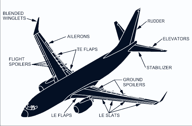
Roll is produced by two ailerons and eight flight spoilers. Pitch is produced by two elevators and a movable horizontal stabiliser. A single rudder controls yaw and becomes aerodynamically effective during the takeoff roll at roughly 40 to 60 knots. Either main hydraulic system can power every primary flight-control axis.
Trailing-edge flaps, leading-edge flaps and slats form the high-lift system. System B normally powers them. If that source is lost, the trailing-edge flaps have an electric alternate drive. The leading-edge devices can receive transferred hydraulic power automatically or can be extended with standby pressure.
Flight-control panel
Each FLT CONTROL switch commands the shutoff valve for its hydraulic source. Selecting STBY RUD starts the standby electric pump and opens the standby rudder shutoff valve. The related LOW PRESSURE light indicates inadequate A or B pressure to the ailerons, elevators and rudder. That light is suppressed after STBY RUD is selected and the standby rudder path opens.
| Indication or control | Meaning or effect |
|---|---|
| STANDBY HYD LOW QUANTITY | Low quantity in the standby reservoir; its monitoring is always armed |
| STANDBY HYD LOW PRESSURE | Low standby-pump output; armed only when standby operation is selected or commanded automatically |
| STBY RUD ON | The standby rudder system has been commanded to pressurise its power-control unit |
| YAW DAMPER | The yaw damper is not engaged |
| FEEL DIFF PRESS | An excessive pressure difference exists in the elevator feel computer |
| SPEED TRIM FAIL or MACH TRIM FAIL | The named trim function has failed; a single flight-control computer channel failure can also produce the light during recall |
Roll control, spoilers and aileron trim
Ailerons and flight spoilers work together for roll. The two control wheels are interconnected, yet transfer mechanisms give the crew a way to isolate a jammed aileron or spoiler path.
Aileron command paths
The captain's wheel is cabled through the aileron feel and centring unit to the aileron power-control units. The first officer's wheel is cabled through the spoiler mixer to the spoiler power-control units. A cable drive connects the wheels, so either wheel normally commands both systems.
If all main hydraulic power is lost, wheel movement can position the ailerons mechanically. Friction and aerodynamic loading make the wheel forces much greater. This manual-reversion capability applies to the ailerons, not to the flight spoilers.
Transfer mechanism and jam response
A jam reveals itself through the force felt at the two wheels. If the aileron path is jammed, the first officer's wheel can retain roll control through the spoilers while the captain's wheel and ailerons are unavailable. If the spoiler path is jammed, the captain's wheel can retain roll through the ailerons while the first officer's wheel and spoilers are unavailable.
Flight spoilers
Four flight spoiler panels are fitted on each wing. Systems A and B power different symmetric spoiler pairs, so loss of one source does not create a one-sided response. The spoiler mixer makes deflection proportional to aileron command. Panels lift on the up-aileron wing but remain faired beside the down aileron. Spoiler assistance begins after control-wheel displacement exceeds about 10 degrees.
Aileron trim
Both AILERON trim switches must be moved together. Electrical trim shifts the feel and centring unit, changes the aileron neutral and turns the control wheel. A scale above each control column shows trim position.
With the autopilot engaged, aileron trim does not move the wheel away from the position held by the autopilot. The trim can therefore build an out-of-trim condition that becomes an abrupt roll when the autopilot is disconnected.
Pitch control and stabiliser trim
The elevators give immediate pitch control through hydraulic power-control units. The stabiliser removes sustained column force and can be moved electrically, by the autopilot or through the manual trim wheels.
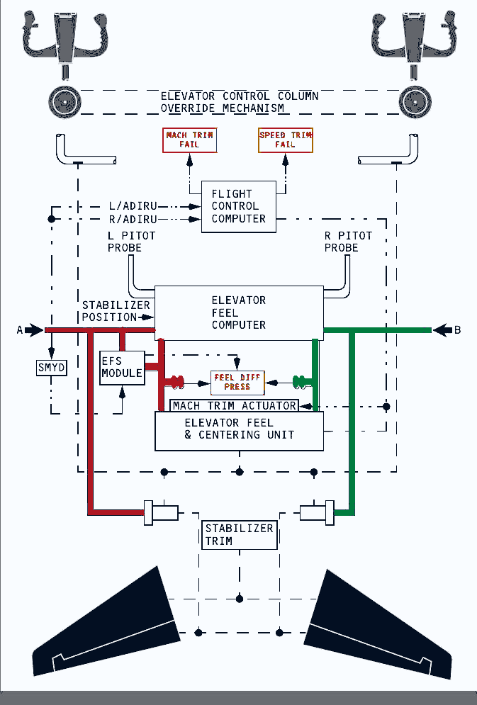
Elevators and column override
The two elevators are joined by a torque tube and are powered by systems A and B. With both hydraulic sources lost, the columns can position the elevators mechanically, but control force rises substantially. If one column path jams, an override mechanism lets the crew break out the free column. Elevator travel is then reduced, although enough remains for a landing flare, and stabiliser trim can relieve the sustained force.
Elevator feel
The elevator feel computer uses stabiliser position and airspeed from the elevator pitot system to create realistic aerodynamic force at the columns. It uses whichever main hydraulic pressure is higher. A hydraulic-source fault or elevator-feel pitot fault can create an excessive internal pressure difference and illuminate FEEL DIFF PRESS.
Stabiliser trim controls
A single electric motor positions the stabiliser from either pair of control-wheel trim switches or from the autopilot trim circuit. Electric trim moves the trim wheels. Moving a pilot trim switch while the autopilot is engaged disconnects the autopilot. Column cutout switches normally stop electric trim when column force opposes trim direction; selecting STAB TRIM OVERRIDE bypasses those column-operated cutouts.
The manual trim wheels remain mechanically connected by cables and override electrical inputs. Two independent brakes hold stabiliser position. Grasping a trim wheel stops stabiliser movement, although manual effort can be high in some conditions.
| Trim mode | Available indicated range for this configuration |
|---|---|
| Main electric, flaps extended | Indicated units 0.05 through 14.5 |
| Main electric, flaps retracted | Indicated units 3.95 through 14.5 |
| Autopilot trim | Indicated units 0.05 through 14.5 |
| Manual trim | Indicated units minus 0.20 through 16.9 |
Mach trim and speed trim
Above Mach 0.615, Mach trim uses air-data inputs and shifts the elevator feel and centring unit to improve high-speed stability. Speed Trim System action supports high-thrust flight at low weight with an aft centre of gravity and the autopilot disengaged. It commands the stabiliser opposite a speed change after considering airspeed, vertical speed, stabiliser position and thrust-lever position. Its Mach gain is fully available from 100 KIAS to Mach 0.60, then fades to zero by Mach 0.68. Other enabling logic includes ten seconds after takeoff, five seconds after pilot trim release and a sensed need for trim.
Rudder, standby control and stall cues
The rudder has two independent main hydraulic channels and a separate standby power-control unit. Monitoring and enhancement functions preserve useful yaw control after several kinds of failure.
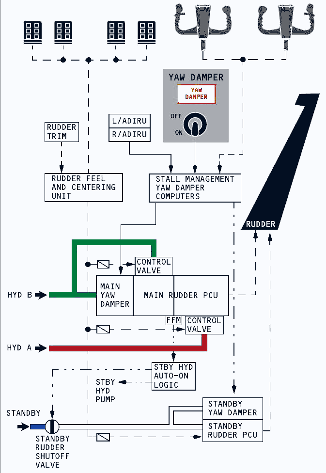
Rudder enhancement and load limiting
The two pedal sets are rigidly connected. Their cables feed independent input rods and control valves for the A and B sections of the main rudder power-control unit. A separate rod and valve command the standby unit. Each input path has jam override, allowing a free path to keep transmitting pedal command if another path is obstructed.
Above 137 knots, rudder load limiting reduces maximum hydraulic pressure in each main channel by about 25 per cent, restricting available rudder travel. Full authority returns below 132 knots. The function operates both in the air and on the ground.
Force-fight monitor and standby rudder
The force-fight monitor looks for opposing A and B actuator pressures, as can occur after a jam or disconnection. A detected disagreement commands the standby hydraulic pump, opens the standby rudder shutoff valve and illuminates STBY RUD ON together with MASTER CAUTION and FLT CONT. Standby operation can also be selected with either FLT CONTROL switch or commanded automatically during takeoff and landing.
Yaw damper and rudder trim
The main and standby yaw dampers receive commands from the stall-management and yaw-damper computers. Either can provide Dutch-roll suppression, gust damping and turn coordination. Its input does not move the pedals and can be overridden by pedal or rudder-trim input. The normal main yaw damper uses hydraulic system B.
A detected yaw-damper fault, a failure to respond or selection of the B FLT CONTROL switch away from ON moves the YAW DAMPER switch to OFF and lights the amber annunciation. During manual reversion, selecting both FLT CONTROL switches to STBY RUD permits the standby yaw damper to be reset ON. Control-wheel motion then supplies roll-coordination assistance through the standby rudder unit.
Rudder trim electrically repositions the rudder feel and centring unit. The pedals move proportionally and the trim indicator shows units of displacement.
Stall identification
The yaw damper, elevator feel shift and speed trim work together as angle of attack rises. The stall-management computer reduces yaw-damper rudder command. Elevator feel shift raises system A pressure to the feel and centring unit, approximately doubling column force. It is inhibited on the ground, below 100 feet radio altitude or with the autopilot engaged. If already active while descending through 100 feet, it remains active until angle of attack falls below approximately the stick-shaker threshold. There is no normal flight deck indication that it is armed or operating.
Speedbrakes and ground spoilers
Flight spoilers can rise symmetrically in the air to increase drag and reduce lift. After touchdown, flight spoilers and the four system A ground spoilers deploy together to dump lift and improve wheel braking.
In-flight use
Moving the SPEED BRAKE lever in flight raises all eight flight spoilers symmetrically. Deployment during a turn can produce a rapid increase in roll rate, especially at intermediate lever positions. Lever movement beyond FLIGHT DETENT causes buffet and is prohibited in flight.
SPEEDBRAKES EXTENDED light
In flight, the amber light warns that the speedbrakes are extended while the aircraft is in landing configuration or below 800 feet AGL. The detailed logic includes lever movement beyond ARMED together with trailing-edge flaps beyond 10, or radio altitude below 800 feet. On the ground, it warns of hydraulic pressure at the ground-spoiler shutoff valve while the lever remains in DOWN.
Automatic deployment from ARMED
For normal touchdown, the lever is in ARMED, its ARMED light is on, radio altitude is below 10 feet, both thrust levers are at IDLE, the main wheels spin above 60 knots and a landing-gear strut compresses. The lever then moves automatically to UP and the spoilers deploy.
Compression of any gear strut enables the flight spoilers. Compression of the right main gear strut mechanically enables the ground spoilers. If wheel spin-up is not sensed, ground-mode logic still moves the lever to UP and deploys the flight spoilers; right-main-strut compression then opens the path for the ground spoilers.
Lever initially in DOWN
During a landing or rejected takeoff with the lever in DOWN, automatic extension requires main-wheel spin above 60 knots, both thrust levers at IDLE and the reverse levers positioned for reverse thrust. Advancing either thrust lever after landing or an RTO drives the SPEED BRAKE lever to DOWN and retracts every spoiler. The crew can also retract them by moving the lever manually to DOWN.
Flaps, slats and load relief
The high-lift system combines double-slotted trailing-edge flaps with four leading-edge flaps and eight slats. Their extension is sequenced so the wing moves through useful takeoff, manoeuvring, approach and landing configurations.
Normal flap schedule
System B normally drives the trailing-edge flaps and leading-edge devices. The lever detents are UP, 1, 2, 5, 10, 15, 25, 30 and 40. Positions 1 through 15 primarily add lift; positions 15 through 40 add both lift and drag. For this configuration, normal landing selections are 15, 30 and 40. Flaps 15 is normally reserved for cases where approach-climb performance drives the landing-flap choice. Do not attempt flap extension higher than 20,000 feet, where Mach effects can impose excessive structural loading.
At lever positions 1, 2 and 5, the leading-edge flaps move fully out and the slats move to their intermediate EXT position. Beyond 5, the flaps remain fully extended while the slats move to FULL EXT. Retraction reverses the sequence. Mechanical gates resist inadvertent lever movement beyond flaps 1 for a one-engine-inoperative go-around and beyond flaps 15 for a normal go-around.
Flap load relief
The Flap Slat Electronic Unit receives the same left-side air-data source used for the captain's airspeed display. If speed is too high for the selected setting, the trailing-edge flaps retract one detent without moving the FLAP lever. They return when speed decreases below the re-extension threshold. This configuration provides load relief only at selected flaps 30 and 40, and not during alternate extension.
| Lever selection | Automatic relief above | Result | Re-extension below |
|---|---|---|---|
| 40 | 163 knots | Trailing-edge flaps move to 30 | 158 knots |
| 30 | 176 knots | Trailing-edge flaps move to 25 | 171 knots |
Autoslats, alternate flaps and protection
Normal high-lift operation includes autoslat support and electronic monitoring. Alternate operation preserves extension capability after a system B loss, but it changes the available directions and removes some protections.
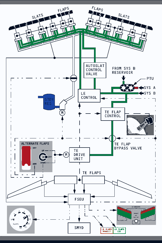
Autoslats and the power transfer unit
Autoslats are available at flap positions 1, 2 and 5 on this configuration. Near a stall, the slats drive from EXT to FULL EXT before stick-shaker activation, then return to EXT after angle of attack is reduced sufficiently. System B normally supplies the pressure. If the high-volume system B engine-driven pump loses pressure, system A drives the power transfer unit, which pressurises system B fluid without transferring fluid between reservoirs.
Alternate extension
Placing the guarded ALTERNATE FLAPS master switch at ARM closes the trailing-edge flap bypass valve, starts the standby pump and enables the position switch. UP electrically retracts the trailing-edge flaps. Holding DOWN drives them electrically towards the chosen position. A momentary DOWN selection also commands the standby hydraulic system to move all leading-edge devices to FULL EXT.
The leading-edge devices cannot be retracted with standby hydraulic pressure. The electric alternate drive provides no trailing-edge asymmetry or skew protection, so monitoring and crew judgement become particularly important.
FSEU monitoring
The Flap Slat Electronic Unit compares left and right high-lift positions. Asymmetry means a device does not match its opposite-side partner. Skew means paired trailing-edge flaps are moving at different rates and can twist. When either condition is detected, the unit closes the trailing-edge bypass valve to stop the drive and preserve symmetry; the position indicator separates its needles to show left and right positions.
For leading-edge improper position, LE FLAPS TRANSIT remains illuminated and the individual-device panel shows whether each device is in transit, at EXT, at FULL EXT or retracted. That transit light is inhibited during normal autoslat movement in flight.
Uncommanded motion
Leading-edge uncommanded motion is recognised when no flap or autoslat command exists and one wing moves two leading-edge flaps, or at least two slats. The FSEU then shuts the leading-edge control and lights LE FLAPS TRANSIT. During cruise it also guards against movement by holding pressure on retract lines while removing pressure from the extension lines.
Trailing-edge uncommanded motion includes movement away from the selected position, continued travel after reaching it or travel opposite the command. The FSEU closes the trailing-edge bypass valve and shuts the drive. The crew cannot reset that shutdown and must use alternate flap control. Here the disagreement is between lever and flap indication; unlike asymmetry or skew, there is no split between the two flap needles.