
Sources and electrical architecture
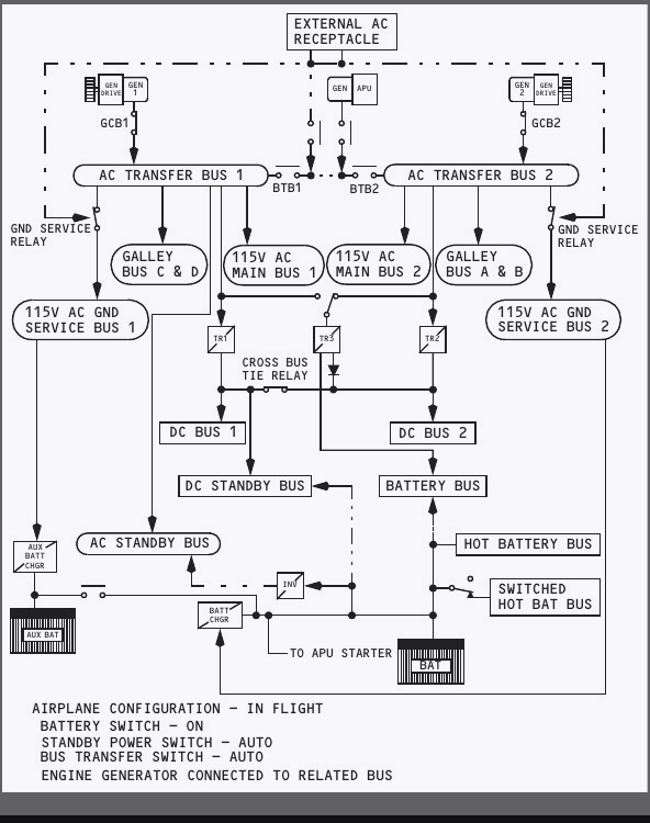
The electrical system accepts power from two engine integrated drive generators, the APU generator, external power and two batteries. Its switching logic keeps the AC supplies separate while making another source available to a bus that loses its normal generator.
Normal AC sources
Each engine drives an integrated drive generator, normally called an IDG. The drive holds generator speed nearly constant over the engine operating range, allowing each generator to produce three-phase, 115 volt, 400 hertz AC. Generator control breakers connect generator 1 to transfer bus 1 and generator 2 to transfer bus 2.
The two AC systems do not operate in parallel. If a different source is connected to a transfer bus, the source already connected to that bus is removed automatically. This break-before-make logic prevents two unsynchronised AC sources from being tied together.
APU and external power
The APU generator may supply either transfer bus or both of them, on the ground or in flight. External AC power can supply both transfer buses on the ground when its voltage and frequency are acceptable. External power and the APU generator cannot be arranged with one supplying each transfer bus. If both are selected, the source selected last takes both buses.
Connecting an engine generator while the APU or external power supplies both buses gives that engine generator its related transfer bus. The previous source remains connected to the other side. In flight, the operating engine generator can take both buses if the other engine generator is lost.
Ground service power
The ground service system lets selected cabin and service loads operate without energising the full aircraft distribution system. It supplies the ground service buses, selected galley and cabin utility loads and the battery chargers. When both transfer buses are powered, their normal feeds override the ground service arrangement.
| Source | Where it can be used | Key switching point |
|---|---|---|
| Engine IDG | In flight or on the ground with its engine running | Normally supplies its related transfer bus |
| APU generator | Ground and flight | Can supply either or both transfer buses |
| External AC | Ground | Can supply both transfer buses when acceptable |
| Batteries | Ground and flight | Supply the standby network when normal AC is lost |
Bus switching and source indications
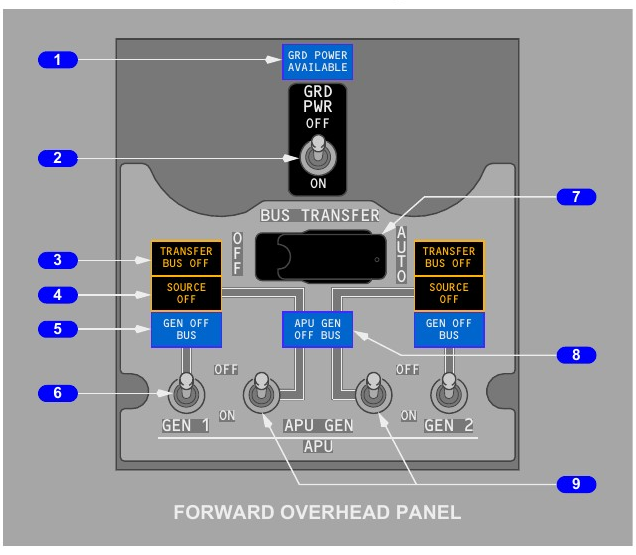
The bus switching panel selects the source. Its lights distinguish a failed bus, a selected source that is no longer feeding its bus and a generator that is running but disconnected.
Ground power
The blue GRD POWER AVAILABLE light means external power is connected and its quality is within limits. Moving the GRD PWR switch momentarily to ON connects it to both transfer buses if the switching conditions are met. Selecting OFF disconnects external power.
Bus transfer control
With BUS TRANSFER in AUTO, the bus tie breakers operate automatically. Loss of a transfer bus source allows an available source to feed that bus through the tie system. Setting the switch OFF isolates the transfer buses, disables automatic transfer and also causes the DC cross bus tie relay to open.
If takeoff is made with the APU generator supplying both transfer buses, an engine generator that has been switched ON can connect automatically once in flight when the APU generator is switched off or fails. This automatic connection is available only once during that flight.
Read the three bus lights separately
| Light | Meaning | Useful distinction |
|---|---|---|
| TRANSFER BUS OFF | The related transfer bus is not powered. | This is a bus condition. |
| SOURCE OFF | The selected source is not supplying its related transfer bus, or no source has been selected. | The bus might still be powered from another source. |
| GEN OFF BUS | The related engine generator is not connected to its bus. | The generator may still be turning. |
| APU GEN OFF BUS | The APU is running and its generator is not connected to a transfer bus. | It identifies an available but disconnected APU source. |
Generator and APU generator switches are spring-loaded. Selecting ON connects the source if it is ready and removes any incompatible source from the affected bus. Selecting OFF trips its generator control breaker.
Generator drives, controls and meters
Generator control protects the AC system, while the drive controls generator speed. The flight crew can disconnect a damaged IDG, but maintenance action on the ground is required before it can be reconnected.
DRIVE light and disconnect
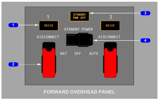
An amber DRIVE light indicates low IDG oil pressure. The cause may be internal IDG failure, engine shutdown, an automatic disconnect after excessive oil temperature, or a completed manual disconnect.
The guarded DISCONNECT switch operates when electrical power is available and the related engine start lever is in IDLE. It mechanically disconnects the IDG from the engine. The unit cannot be reconnected in flight and must be restored by maintenance on the ground.
AC and DC metering
The AC meter selector can display voltage and frequency for standby power, ground power, generator 1, the APU generator, generator 2 and the static inverter. Generator frequency appears only while that generator is electrically excited. AC current can be checked for both engine IDGs and the APU generator.
The DC selector gives voltage and current for the main battery and each of the three transformer rectifiers. The standby power and battery bus selector positions show voltage only. TEST positions are intended for maintenance checks.
| Selection | What the meters can show |
|---|---|
| Engine or APU generator | AC volts, frequency and current |
| Ground power or inverter | AC volts and frequency |
| Battery or TR1, TR2, TR3 | DC volts and current |
| DC standby or battery bus | DC volts only |
Protective control
Generator control includes voltage regulation and protective tripping. A generator that is not within acceptable parameters is disconnected from the buses. The transfer logic can then connect another usable source without paralleling it with the failed source.
Automatic load shedding
When available generation is less than the connected demand, the system removes discretionary cabin loads in a fixed order. Flight-critical buses remain supported while galley, main cabin and entertainment loads are reduced.
One engine generator supplying both sides
If a single engine generator is carrying both transfer buses and the load is excessive, the system first removes galley and main cabin loads associated with transfer bus 2. If the overload remains, equivalent loads on transfer bus 1 are removed. In-flight entertainment is the next load to be shed if more reduction is needed.
With two engine generators restored, automatically shed loads are restored automatically. The crew can attempt a manual restoration by moving CAB/UTIL OFF and then ON, but the system will shed the loads again if the overload persists.
APU generator carrying the aircraft
In flight with the APU generator as the only AC source, galley and main cabin loads are removed. If the remaining demand is still too high, in-flight entertainment is shed. On the ground, the APU generator first attempts to carry the complete connected load and sheds galley and main cabin loads only if required.
| Operating condition | Initial load-shed action | If demand remains high |
|---|---|---|
| One engine generator powers both transfer buses | Transfer bus 2 galley and main cabin loads | Transfer bus 1 galley and main cabin loads, then entertainment |
| APU generator alone in flight | All galley and main cabin loads | Entertainment |
| APU generator alone on the ground | Attempts the full connected load | Galley and main cabin loads are shed if necessary |
Crew interpretation
Loss of cabin utility power can therefore be an automatic protective response rather than a separate fault. Establish the source configuration first, then use the lights and electrical indications to decide whether load shedding is expected.
DC power and transformer rectifiers
Three transformer rectifier units convert the main AC supply into 28 volt DC. Their normal feeds and cross-tie arrangement give the DC system enough redundancy for any two units to carry the connected load.
TR feeds and normal duties
TR1 is supplied by AC transfer bus 1. TR2 is supplied by AC transfer bus 2. With BUS TRANSFER in AUTO, TR3 normally uses AC transfer bus 2 and has AC transfer bus 1 as an alternate feed.
During normal operation, the cross bus tie relay links both main DC buses with the standby DC bus. TR1 and TR2 therefore share those three buses. TR3 normally supplies the battery bus and also backs up TR1 and TR2.
| Unit | Normal AC input | Normal DC role |
|---|---|---|
| TR1 | AC transfer bus 1 | Shares DC bus 1, DC bus 2 and DC standby bus |
| TR2 | AC transfer bus 2 | Shares DC bus 1, DC bus 2 and DC standby bus |
| TR3 | AC transfer bus 2, with transfer bus 1 backup in AUTO | Normally supplies battery bus and backs up TR1 or TR2 |
Cross bus isolation
The cross bus tie relay opens when BUS TRANSFER is moved to OFF. It also opens when the glideslope is captured on an ILS flown with the flight director or autopilot. That approach isolation prevents one DC fault from affecting both navigation receivers and both flight control computers.
TR UNIT and ELEC lights
On the ground, any failed transformer rectifier illuminates the amber TR UNIT light. In flight, the light comes on for failure of TR1, or for the combined failure of TR2 and TR3. A single TR2 or single TR3 failure in flight does not by itself illuminate the light.
The amber ELEC light indicates a fault in the DC or standby power system. It operates only on the ground and is inhibited in flight.
Dual batteries and battery chargers
This aircraft has a main battery and an auxiliary battery. Both are 24 volt nickel-cadmium units, but the auxiliary battery remains isolated until the batteries are required to support the standby system.
Capacity and normal connection
When standby power is being supplied by batteries, the auxiliary battery connects in parallel with the main battery. At other times it is isolated from the distribution network. Two fully charged batteries provide standby power for at least 60 minutes. The specified battery voltage range is 22 to 30 volts.
After both generators are lost, battery power supports the battery bus and DC standby bus, together with the hot and switched hot battery buses. The hot battery bus has a permanent connection to the battery. The switched hot battery bus is powered when the BAT switch is ON.
The amber BAT DISCHARGE light warns that excessive discharge has been detected. If BAT is selected OFF while the battery is the only source, power is lost from the battery and DC standby buses, the switched hot battery bus and the static inverter.
Two charger arrangements
AC ground service bus 2 supplies the main charger, while AC ground service bus 1 supplies the auxiliary charger. Each charger restores its battery and maintains charge automatically.
After the main battery completes its primary charging cycle, its charger operates as a constant-voltage transformer rectifier. In that mode it supports the hot and switched hot battery bus loads. It can also supply the battery bus if TR3 fails.
| Item | Normal condition | Standby condition |
|---|---|---|
| Main battery | Connected to its normal battery network | Shares standby demand with auxiliary battery |
| Auxiliary battery | Isolated from distribution | Connected in parallel with main battery |
| Main charger | Fed by ground service bus 2 | Can support battery bus if TR3 is lost |
| Auxiliary charger | Fed by ground service bus 1 | Supports charging of the auxiliary battery |
Standby power and total generator loss
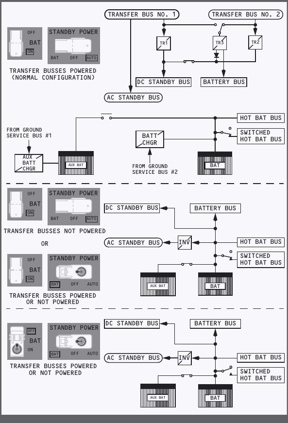
The standby system keeps selected essential 115 volt AC and 24 volt DC services available after normal engine and APU generated AC is lost. Automatic changeover depends on the BAT switch being ON and the guarded STANDBY POWER switch being in AUTO.
Normal and alternate feeds
In the normal AUTO configuration, AC transfer bus 1 supplies the AC standby bus. TR1, TR2 and TR3 make power available to the DC standby bus, while TR3 supplies the battery bus. The batteries and chargers support the hot battery buses.
AUTO changes the affected standby supply after loss of either its AC feed from transfer bus 1 or its DC feed from bus 1. If all engine and APU AC power is lost, the two batteries supply the standby network in flight or on the ground. Their 24 volt DC output feeds the DC standby and battery buses directly. The static inverter converts battery DC to 115 volt AC for the AC standby bus.
STANDBY POWER switch
| Position | Result |
|---|---|
| AUTO | Uses normal bus sources and automatically changes to battery sources when the required normal supply is lost. |
| BAT | Overrides automatic logic and puts the AC standby, DC standby and battery buses on battery power. |
| OFF | Removes power from the AC and DC standby buses and illuminates STANDBY PWR OFF. |
The amber STANDBY PWR OFF light illuminates when any of these buses is unpowered: AC standby, DC standby or battery bus.
What remains after all generators are lost
Battery-only operation preserves selected essentials rather than the full aircraft. On this configuration the Captain retains a primary flight display, navigation display and the integrated standby flight display. The clock, left EFIS controls, navigation receiver set, left IRS and GPS, transponder 1, VHF 1, interphones and passenger address remain among the supported services.
Essential engine indications remain on the upper display. Fire detection and extinguishing, fuel shutoff control, selected hydraulic and landing-gear functions, stall warning, aural warnings and master caution recall also remain. The right ignition system is available. APU operation is supported, but a start attempt above 25,000 feet is not recommended.