
Normal gear operation and indications
This aircraft has two twin-wheel main gears and one steerable twin-wheel nose gear. System A is the normal hydraulic source for gear movement and nose-wheel steering. The cockpit panel combines the selector, position lights and operating-speed placard.
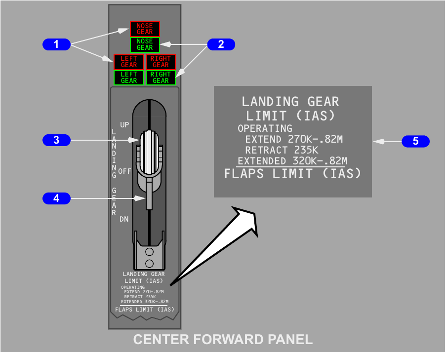
Lever positions and lock
UP commands retraction. DN commands extension. OFF removes hydraulic pressure from the gear circuit after retraction. On the ground, a mechanical lock prevents an UP selection. An override trigger can bypass that lock, while the air-ground system releases it electrically in flight.
| Indication | Condition | Meaning |
|---|---|---|
| Upper red light | Related gear disagrees with the lever, is moving or is unsafe | The commanded position has not been achieved |
| Upper red light near landing | Either forward thrust lever is at idle, the aircraft is below 800 feet AGL and a gear is not down and locked | A landing configuration hazard exists |
| Lower green light | Related gear is down and mechanically locked | One green indication for each gear, on either the centre or overhead set, confirms the down-and-locked condition |
There is a separate green-light set on the aft overhead panel. All three gears being down and locked suppresses the landing-gear warning horn. A red light is normally out when its gear agrees with the selected UP, OFF or DN state.
Retraction
Moving the lever UP starts hydraulic retraction. The wheel brakes stop the main wheels before they enter their wells. Mechanical uplocks retain both main gears; outboard wheel hubcaps and seals complete the aerodynamic fairing. The nose wheels travel forward, snubbers arrest their rotation, and an overcentre device holds the nose gear while doors linked to the mechanism close around it.
A damaged main-gear tyre can interfere with wheel braking during retraction. If a loose, rotating tread contacts the wheel-well ring fitting, retraction stops and that gear falls back down. The gear then remains unavailable for retraction until the fitting is repaired.
Normal extension
With DN selected, system A releases the uplocks. Hydraulic force, gravity and airflow move the gear to full extension. Mechanical overcentre locks, supported hydraulically, secure the down position. The nose-gear doors stay open with the gear extended.
Transfer pressure and manual extension
Two backup ideas must be kept separate. The landing-gear transfer valve supplies system B flow for a normal-rate retraction when the system A engine pump loses volume. Manual extension releases uplocks so gravity and airflow can lower the gear without hydraulic pressure.
Landing-gear transfer valve
System B engine-pump flow reaches the gear through the transfer valve when four conditions exist together: the aircraft is airborne, engine 1 RPM is below its trigger, the gear lever is UP, and at least one main gear is not yet up and locked. The purpose is to preserve a normal retraction rate after loss of the system A engine-pump contribution.
Manual access and handles
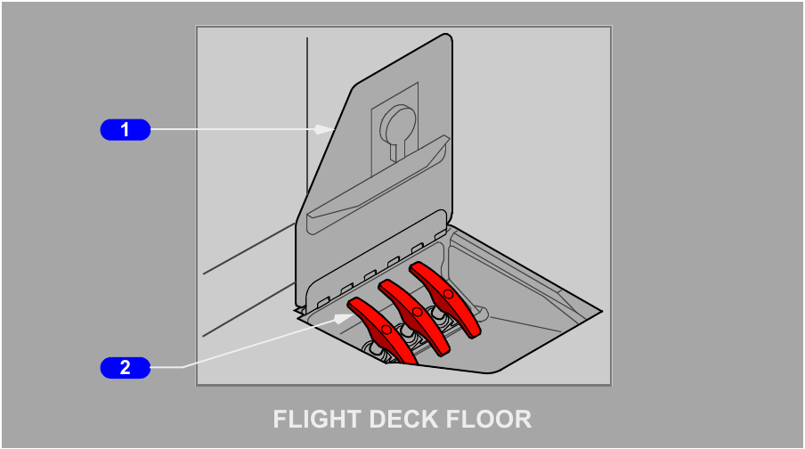
Opening the floor access door makes the three release handles available. Each handle must be pulled to its stop, about 24 inches or 61 centimetres, to release the corresponding uplock. Once released, gravity and air loads take that gear towards the down-and-locked position.
| Access door state | Manual extension | Normal hydraulic operation |
|---|---|---|
| Closed | Handles stowed | Normal extension and retraction available |
| Open | Can be used with the gear lever in any position | Normal extension remains possible if system A pressure exists, but retraction is inhibited |
Returning to normal retraction
After a manual extension, first close the access door. With system A pressure available, move the gear lever to DN so the normal system is restored to an extension state, then select UP for retraction.
Nose-wheel steering
Steering becomes available when the nose gear is down and compressed by aircraft weight. The tiller provides the large steering range needed for taxi, while the rudder pedals give a smaller range for directional corrections.
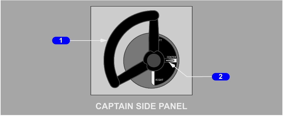
Normal and alternate sources
With the steering switch guarded at NORM, system A supplies the steering metering valve after the gear lever is placed DN. Selecting ALT substitutes system B pressure. Alternate steering requires the aircraft on the ground and a normal quantity in the system B reservoir.
If the pipework beyond the gear transfer valve leaks, system B can be drained. A sensor then closes the transfer valve, so alternate nose-wheel steering is also lost. This protects the remaining system from the leaking branch.
Tiller and rudder pedals
| Input | Steering authority | Relationship |
|---|---|---|
| Nose-wheel steering tiller | Up to 78 degrees left or right | Overrides any rudder-pedal steering input |
| Full rudder-pedal movement | Up to 7 degrees left or right | Available for limited steering while the nose strut is compressed |
| Top of brake pedal | No steering command | Applies the wheel brakes |
As the nose strut extends, pedal steering is removed. A towing lockout pin can depressurise the steering actuator at the towing lever, allowing pushback or towing without depressurising the rest of the hydraulic system.
Brakes, accumulator and antiskid
Each main wheel has a hydraulic multi-disc brake, and the left and right pedal inputs are independent. The nose wheels are unbraked. Normal, alternate and stored-pressure paths give several layers of stopping capability.
Pressure sources
| Brake mode | Pressure source | Availability |
|---|---|---|
| Normal brakes | Hydraulic system B | Normal pedal braking and the only source for autobrake operation |
| Alternate brakes | Hydraulic system A | Selected automatically when system B is low or unavailable |
| Accumulator braking | Pressure stored from system B | Several pedal applications or a parking-brake application after both systems lose pressure |
The HYD BRAKE PRESS gauge reads accumulator pressure. For this configuration, the normal band is 2900 to 3600 psi, the maximum band extends from 3600 to 4000 psi, and normal precharge is 1000 psi.
Antiskid comparison
Both hydraulic brake paths include antiskid. With normal braking, each of the four main wheels has independent skid control. Alternate braking groups the wheels into left and right main-gear pairs. When a skid is sensed, the appropriate valve reduces pressure until wheel rotation recovers.
Both modes protect against wheel lock, touchdown wheel-up braking and hydroplaning as well as an ordinary skid. Antiskid control remains available after both main hydraulic systems are lost, allowing it to regulate accumulator pressure. ANTISKID INOP illuminates amber when monitoring detects a fault and is out when the system is operating normally.
Pedal operation
Pressing the upper portion of a pedal applies its related brakes. The pedal mechanism provides separate left and right control, allowing differential braking when needed. Full pedal travel also commands the limited nose-wheel steering range described on the previous page.
Autobrake, parking brake and air-ground logic
Autobrake uses normal system B brake pressure and retains antiskid protection. RTO commands maximum pressure after a qualifying rejected takeoff, while landing selections 1, 2, 3 and MAX regulate to a chosen deceleration rate.
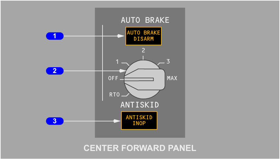
Rejected-takeoff mode
RTO can be selected only with ground logic. A successful selection produces a one-to-two-second AUTO BRAKE DISARM light test. Arming requires both antiskid and autobrake healthy, RTO selected, wheel speed below 60 knots, the aircraft on the ground and both forward thrust levers at IDLE.
If the takeoff is rejected below 88 knots, automatic braking does not start and RTO remains armed. At 88 knots or more, retarding the forward thrust levers to IDLE commands maximum brake pressure. RTO disarms when both air-ground channels change to air, without illuminating the disarm light and without moving the selector.
Landing with RTO still selected produces no automatic braking. The disarm light appears about two seconds after touchdown. Cycling the selector through OFF resets or manually disarms the mode.
Landing autobrake
Selecting a landing setting initiates a self-test. A failed test illuminates AUTO BRAKE DISARM and prevents arming. Following touchdown, braking begins after both forward thrust levers reach IDLE and the main wheels spin up. A setting may also be selected after touchdown before deceleration through 30 knots, with immediate application if the other conditions already exist.
The controller reduces brake pressure when spoilers or reverse thrust add deceleration. The selector can be moved to a different landing level without disarming. The system continues to a complete stop unless a pilot terminates automatic braking. On a dry runway, even MAX landing autobrake gives less deceleration than full manual pedal braking.
After braking starts, manual brake application, moving the SPEED BRAKE lever to its down detent, or advancing a forward thrust lever disarms autobrake and illuminates AUTO BRAKE DISARM. Thrust advancement during the first three seconds after touchdown is excluded from that last trigger. Moving the selector directly to OFF disarms without lighting the warning.
Parking brake
Either main hydraulic system can provide parking-brake pressure. With both systems depressurised, the accumulator maintains it. To set the brake, fully depress both pedals and pull the PARKING BRAKE lever aft; pedal pressure latches mechanically and the parking valve closes. Pressing the pedals again releases the lever.
The red PARKING BRAKE light uses battery power. A parking-brake fault can illuminate ANTISKID INOP. Advancing a forward thrust lever for takeoff while the parking brake remains set produces the takeoff-configuration lights and warning horn.
Air-ground sensing
Six sensors, two on each landing gear, tell aircraft systems whether the aeroplane is in the air or on the ground. Their logic releases the gear-lever lock and enables the transfer valve in flight, changes touchdown antiskid and autobrake behaviour, and enables takeoff warning on the ground.
The same state is distributed beyond this chapter. In flight, emergency-exit flight locks engage when either engine N2 exceeds 50 percent and at least three entry or service doors are closed. Autothrottle go-around is available below 2000 feet radio altitude in the air mode. Other users include pressurisation, wing anti-ice, recorders, thrust reversers, standby hydraulics and stall warning.