
Controls, indications and trip logic
Air systems share one operating idea: bleed air is admitted, cooled, distributed and finally released in controlled amounts. The overhead panel lets the crew command that process and recognise heat, pressure or controller faults before studying the detailed airflow.
What the main annunciations mean
| Indication | Meaning | Automatic protection or crew follow-up |
|---|---|---|
| WING-BODY OVERHEAT | A detector has sensed a hot-air leak in the associated wing or body duct zone. | Use the non-normal procedure to isolate the source. The TEST selection checks both detector loops and lights both indications. |
| BLEED TRIP OFF | The associated engine bleed has encountered excessive temperature or pressure. | The engine bleed air valve closes. After the cause is removed, TRIP RESET is used to restore the system. |
| PACK | The pack has tripped, or both its normal and standby control channels have failed. | An overheat closes the pack valve. Recall can identify a single controller failure that has not stopped the pack. |
| ZONE TEMP | A cabin-zone duct has overheated. CONT CAB can also indicate failure of both flight-deck temperature-control channels. | The affected trim-air valve closes after a duct overheat. Reset becomes possible after cooling. |
| AUTO FAIL | The active pressurisation controller or its control path has failed, or a protected pressure condition has been exceeded. | Control normally transfers to the alternate automatic controller. |
Switch logic and reset discipline
Each engine BLEED switch commands its bleed valve. The APU BLEED switch controls the APU source, while the isolation-valve selector determines whether the left and right manifolds are separated or connected. PACK switches command OFF, AUTO or HIGH flow. RECIRC FAN switches reduce the amount of fresh conditioned air that the packs must supply.
TRIP RESET is not a way to suppress a warning. It attempts to reopen a tripped engine bleed valve and resets pack or zone overheat logic only after temperature and pressure have returned to an acceptable condition. A warning that returns identifies a condition that still exists.
Temperature and pressure instruments
The duct-pressure indicator compares the left and right pneumatic manifolds. Unequal indications can be normal, provided the operating source supplies enough air. The cabin-altitude panel combines cabin altitude, differential pressure, cabin rate and outflow-valve position. The cabin-altitude needle may travel below zero or to the top of its scale, so the crew reads the instrument rather than assuming that zero is its lower stop.
Bleed sources, ducts and isolation
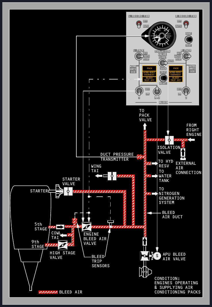
The pneumatic manifold can receive air from either engine, the APU or a ground cart. It then supports conditioning, pressurisation, engine starting, thermal anti-ice and several smaller services.
Engine extraction and regulation
Engine bleed air normally comes from the fifth compressor stage. The ninth stage supplements it when pressure from the fifth stage is insufficient, especially at low engine power. A high-stage valve governs that extra supply. The engine bleed air valve both shuts off and regulates the source. Its command is electrical, while pneumatic pressure provides the operating force.
Protective sensors guard against excessive pressure and temperature. A detected trip closes the related engine bleed valve and illuminates BLEED TRIP OFF. Hot-air leak detectors monitor the wing leading-edge ducts, engine-strut areas, air-conditioning bays, keel-beam region, APU supply duct and adjacent body sections represented by the left and right warning channels.
The isolation valve in AUTO
A closed isolation valve divides the manifold into left and right halves. In AUTO, it remains closed when both engine BLEED switches are ON and both PACK switches are in AUTO or HIGH. It opens when either engine BLEED switch is OFF or either PACK switch is OFF. The APU BLEED switch does not by itself change that AUTO decision.
The APU bleed valve is electrically commanded and pneumatically moved. It shuts when the APU is stopped. If an APU source and an engine source are connected while the engine is at idle, APU pressure can hold an engine high-stage valve closed. DUAL BLEED then warns against advancing thrust until the conflicting source arrangement is corrected.
Packs, airflow and the cooling cycle
A pack converts hot pneumatic air into temperature-controlled air. The system balances cooling demand against available bleed capacity, then mixes the two pack streams with recirculated cabin air.
Normal supply arrangements
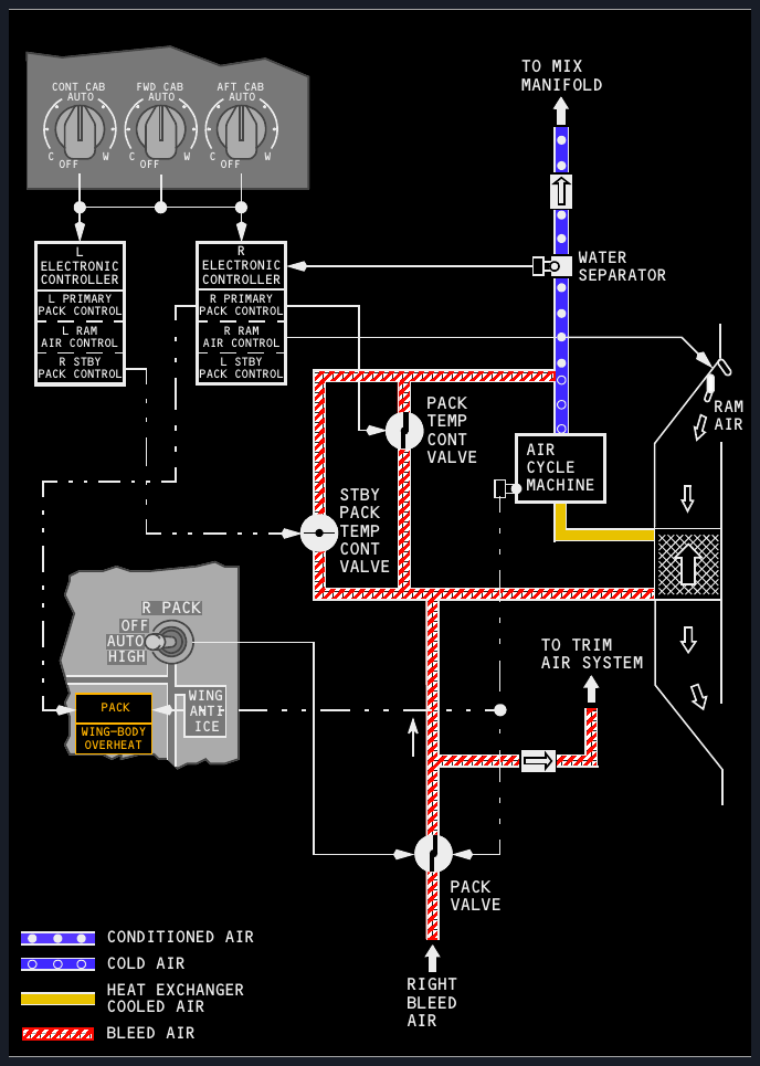
The left engine normally supplies the left pack and the right engine supplies the right pack. Left-pack air serves the flight deck first; surplus left-pack flow, right-pack flow and recirculated air meet in the mix manifold. A connected ground-conditioning source also feeds that manifold.
One pack in HIGH can maintain pressurisation and temperature control through the certified ceiling. The APU can normally support both packs on the ground or one pack in flight. Most external pneumatic carts can operate both packs. Operating two packs from one engine is prohibited because the single engine source is not intended to support that demand.
| Condition | Flow response | Reason |
|---|---|---|
| Both packs in AUTO | Normal pack flow | Provides the scheduled fresh-air supply with normal bleed demand. |
| One pack unavailable in flight with flaps up | The operating pack increases to high flow automatically. | Replaces part of the lost conditioned-air capacity. |
| One pack unavailable on the ground, or in flight with flaps down | Automatic high flow is inhibited with an engine bleed source. | Preserves engine performance during high-demand phases. |
| APU is the only bleed source | A remaining pack can increase automatically, independent of the flap or air-ground state. | APU high-flow scheduling supports ventilation without taking engine thrust. |
| Either pack selected HIGH on APU bleed | APU commands maximum pneumatic delivery. | Meets the requested high-flow pack demand. |
Cooling cycle
Bleed air first loses heat in the primary heat exchanger. The air-cycle machine then compresses the stream, which raises its temperature, before the secondary heat exchanger removes more heat. Expansion through the turbine produces the major temperature drop and drives the compressor and fan. A water separator removes condensed moisture. A controlled bypass of warmer air prevents excessive cooling and gives the pack its commanded outlet temperature.
Ram air passes through the heat exchangers. Its inlet doors are fully open on the ground and at low speed with flaps not retracted, then modulate in cruise. A deflector reduces slush ingestion. Overtemperature protection closes the pack valve and lights PACK.
Zone control, distribution and equipment cooling
Pack outlet temperature is only the starting point. The three-zone system then adds controlled trim air, combines fresh and recirculated flow, and routes separate cooling air through the electronic equipment spaces.
Three-zone temperature control
The controlled zones are CONT CAB, FWD CAB and AFT CAB. Each selector covers approximately 65 to 85 degrees Fahrenheit, or 18 to 30 degrees Celsius. The pack system first satisfies the zone asking for the greatest cooling. Hot trim air is then metered into the other zone ducts to reach their selected temperatures.
With one pack operating and TRIM AIR ON, control remains similar to the two-pack case. With TRIM AIR OFF, pack temperature is based on an average demand and the zone trim valves are closed. An overheated zone duct closes its trim valve and illuminates the related ZONE TEMP light.
Controller failures progressively simplify the system. A passenger-zone control failure substitutes an averaged demand. Loss of all zone and normal pack-control channels puts the standby pack controllers in charge using the two cabin-zone signals; trim valves close and the flight-deck selector no longer controls outlet temperature. If all three zone selectors are OFF, the left pack regulates near 75 degrees Fahrenheit or 24 degrees Celsius, and the right pack near 65 degrees Fahrenheit or 18 degrees Celsius.
Recirculation and airflow
Recirculation fans return filtered cabin air to the mix manifold. This reduces pack workload and engine bleed demand. In flight, the left fan stops when either pack is in HIGH, while the right fan stops only when both packs are in HIGH. During ground operation, dual HIGH selection stops the left fan; the right fan keeps running.
Conditioned air reaches the flight deck through risers, floor outlets and overhead diffusers. Foot-warm and windscreen-demist valves let each pilot direct additional warm air. Cabin air also flows around the cargo-compartment linings, helping heat those spaces before discharge.
Electronic equipment cooling
Normal and alternate supply and exhaust fans move cooling air through the electronic bays. Selecting the alternate fan should restore the associated flow indication in about five seconds. The system also protects the forward cargo compartment during a fire warning by changing exhaust operation and suppressing a misleading fan-off indication for the defined smoke-control period.
For this configuration, selecting both RECIRC FAN switches OFF and both PACK switches HIGH makes the smoke-control relay stop the equipment-cooling supply fan for five minutes, suppress the related OFF lights for the same period, and stop the exhaust fan for the rest of the flight. Moving one of those four switches away from that arrangement restarts electronic-equipment cooling. On the ground, an equipment-cooling overheat can also sound the crew-call horn in the nosewheel well.
Pressurisation architecture and outflow
Pressurisation does not create air independently. The packs supply mass flow, and the pressure controller regulates how quickly that air is allowed to leave through the outflow system.
Control modes and inputs
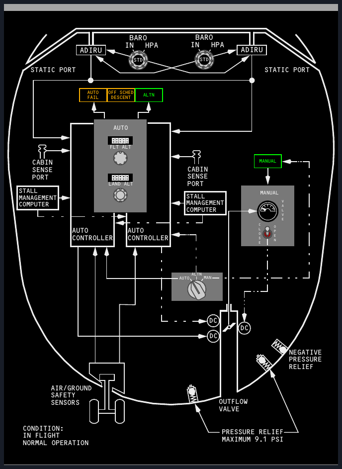
Two identical automatic controllers support AUTO and ALTN. They alternate the primary role between flights, leaving the other ready as a backup. MAN gives the pilots direct electrical control of the outflow valve. All three modes use a DC motor, but manual operation uses a separate motor powered by the standby DC system.
The automatic controllers receive ambient pressure, barometrically corrected altitude, uncorrected altitude and calibrated airspeed from the air-data inertial units. Pilot barometric selections provide the correction. Thrust-lever position arrives through the stall-management computers, and air-ground sensing tells the system which flight phase is active. Cabin-sense ports close the loop.
Outflow and structural protection
The main outflow valve releases most cabin air. Smaller quantities leave through fixed leaks and galley, lavatory and toilet vents. Cabin air travels through foot-level grilles, around the aft cargo lining for heating, and then to the outflow valve.
The overboard exhaust valve is open on the ground and during low-differential flight, allowing warm electronic-equipment exhaust to leave directly. At higher differential pressure it normally closes, routing that warm flow around the forward cargo lining. In the smoke-removal configuration used here, either pack in HIGH together with the right recirculation fan OFF commands the valve open for increased ventilation.
Two positive pressure-relief valves limit differential pressure to 9.1 psi. A negative-relief valve prevents outside atmospheric pressure from becoming greater than cabin pressure. Under normal control, the system targets a cabin altitude of 8,000 ft at the aircraft's 41,000 ft certified ceiling.
Automatic schedule, limits and manual control
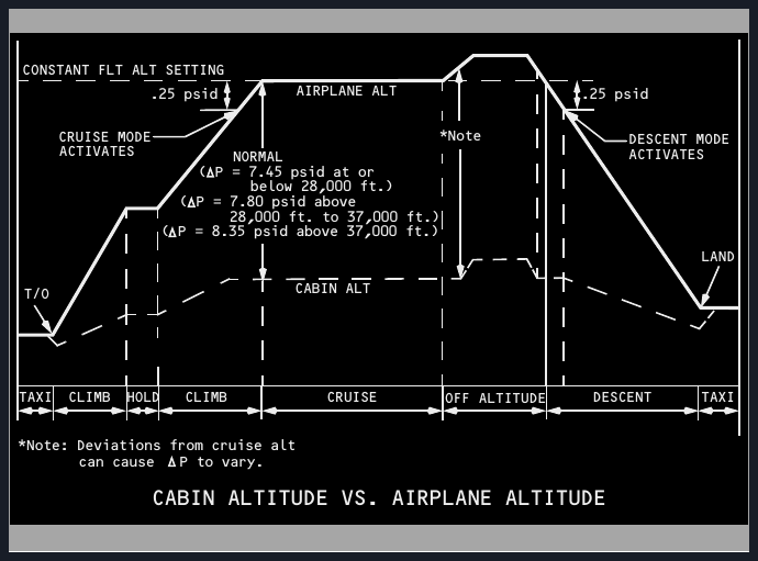
The automatic controller uses the selected cruise and landing altitudes to build a complete pressure schedule from taxi out to taxi in. Understanding each transition makes the warning logic easier to interpret.
Selections and flight phases
FLT ALT can be set from minus 1,000 ft to 42,000 ft in 500 ft increments. LAND ALT covers minus 1,000 ft to 14,000 ft in 50 ft increments. On the ground, the sensed takeoff-field elevation is also retained by the controllers.
At low ground power the outflow valve is fully open and the cabin is depressurised. Higher takeoff power moves it partly closed to give slight prepressurisation and smooth the lift-off transition. During climb, cabin altitude rises at a rate proportionate to aircraft climb. Cruise mode engages when aircraft pressure reaches within 0.25 psi of the selected FLT ALT.
If descent starts before the preset cruise altitude is reached, OFF SCHED DESCENT announces the abort schedule. The controller then aims to return the cabin to takeoff-field elevation. Changing FLT ALT removes that original-field abort target.
| Selected flight-altitude band | Normal differential-pressure limit |
|---|---|
| At or below 28,000 ft | 7.45 psid |
| Above 28,000 ft through 37,000 ft | 7.80 psid |
| Above 37,000 ft | 8.35 psid |
Descent mode begins when aircraft pressure moves 0.25 psi below the selected FLT ALT reference. Cabin altitude then follows a proportional descent to slightly below the selected LAND ALT, leaving a small positive pressure for touchdown. During taxi in, the valve opens gradually until the cabin is depressurised.
Automatic failure and alternate control
AUTO FAIL illuminates for loss of DC supply, a controller fault or an outflow-valve control fault. If the active controller does not respond properly, protection also reacts above 8.75 psi differential, when cabin rate exceeds approximately 2,000 sea-level feet per minute in either direction, or when cabin altitude exceeds 15,800 ft. The system transfers to the other automatic controller. Selecting ALTN clears AUTO FAIL while ALTN stays illuminated to show single-channel operation.
The cabin-altitude warning horn sounds at 10,000 ft cabin altitude. This is a crew alert and is distinct from the higher automatic-controller failure threshold.
Manual mode
MAN is used when both automatic modes are unavailable or when a non-normal procedure directs it. The outflow-valve switch drives the separate standby-powered motor. It is faster than automatic control, although full valve travel can still take up to 20 seconds. The crew monitors both valve position and cabin instruments continuously.
The pressure figures on this page explain system control and protection. Certified aircraft operating limitations remain in the dedicated limitations chapter and the applicable operating manual.