
Engine architecture and airflow
Two CFM56-7 series turbofan engines power the aircraft. Each engine contains two mechanically independent rotating systems, with N1 describing the low-pressure rotor and N2 describing the high-pressure rotor.
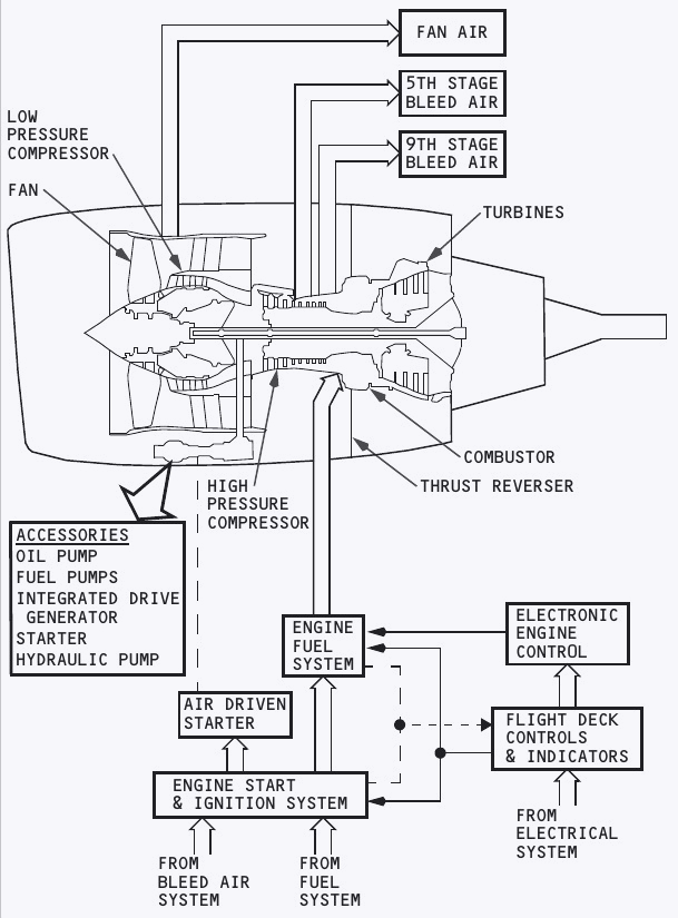
The two rotors
The N1 rotor includes the fan, low-pressure compressor and low-pressure turbine. The N2 rotor contains the high-pressure compressor and high-pressure turbine. A shaft for each rotor connects its compressor to its turbine, but the shafts are not mechanically locked to one another.
Air entering the engine divides into core flow and bypass flow. Core air is compressed, mixed with fuel and burned in the combustor, then expands through the turbines. Most air passes around the core as fan discharge. That bypass stream produces much of the forward thrust and is redirected by the thrust reverser after landing.
Accessory and bleed connections
The N2 system drives the engine accessory gearboxes. Driven units include the oil and fuel pumps, integrated drive generator and hydraulic pump. The air-driven starter also turns N2 through the gearbox during a start.
Compressor air is tapped for the pneumatic system. Fifth-stage bleed is the normal low-stage source, while ninth-stage air provides a higher-pressure source when system demand requires it. Fan air supports cooling functions.
Control path
Each engine has a dual-channel electronic engine control, or EEC. It receives flight-deck commands, sensed atmospheric conditions and bleed demand, then meters fuel to obtain the commanded N1. The thrust levers can be moved by the autothrottle or by the flight crew.
| Item | Main elements | Practical role |
|---|---|---|
| N1 rotor | Fan, low-pressure compressor and turbine | Produces most thrust through the fan stream |
| N2 rotor | High-pressure compressor and turbine | Drives the gearboxes and supports starting |
| EEC | Two independent control channels | Controls fuel and schedules thrust |
| Accessory gearbox | Pumps, generator and starter connection | Transfers N2 rotation to engine accessories |
Engine displays and crew alerts
The display system separates primary thrust information from secondary condition information. Colour, pointer position, boxes and automatic display changes help the crew identify an exceedance without replacing the required checklist response.
Primary and secondary indications
The two primary parameters are N1 and EGT, normally presented on the upper display unit. If that unit fails, they transfer automatically to the lower display. The crew can also select engine data to an inboard display.
The secondary set comprises N2 and fuel flow, followed by oil pressure, quantity, temperature and vibration. On this configuration fuel flow is continuously shown below the primary data, while the other secondary values are selected with the ENG display control. They appear automatically at initial electrical power, after an in-flight start lever is moved to CUTOFF, when an engine falls below idle in flight, or when a secondary parameter exceeds its normal range.
If the lower display is unavailable, primary and secondary values can be combined in compact format. N1 and EGT retain their dial presentations, while the other parameters are reduced to digital values.
Colour and exceedance logic
| Presentation | Meaning |
|---|---|
| White value or pointer | Normal operating range |
| Amber value, box or band | Caution range or maximum continuous EGT exceedance |
| Red value, box or redline | Operating limit or applicable start limit exceeded |
| Reverse video | Used for conditions such as low oil quantity or high vibration |
EGT has a red operating limit, an amber maximum-continuous band and, during applicable starts, a separate red start limit. On this aircraft an amber colour change for maximum-continuous EGT is suppressed for as long as 5 minutes during takeoff or go-around. If an engine-out condition begins within the first 5 minutes, the suppression can extend to 10 minutes.
Specific alerts
ENG FAIL appears on an EGT indication when the start lever is at IDLE and the engine is below sustainable idle, defined as less than 50 percent N2. The message clears after recovery, movement of the start lever to CUTOFF, or pulling the engine fire switch.
START VALVE OPEN, LOW OIL PRESSURE and OIL FILTER BYPASS can flash with attention boxes for 10 seconds before remaining steady. Flashing is inhibited from 80 knots on takeoff until the first of 400 feet radio altitude or 30 seconds after reaching 80 knots. It is also inhibited below 200 feet radio altitude on landing until 30 seconds after touchdown.
Electronic engine control and idle logic
The EEC is a full-authority digital controller. It alternates between two internal channels for successive starts, automatically transfers channels after a channel fault and provides normal, soft-alternate and hard-alternate operating modes.
Normal mode
In normal mode the EEC combines air data, bleed demand and thrust-lever position to calculate an N1 rating. It compares the commanded and actual N1, then changes fuel flow through the hydromechanical unit to close the difference. Full rated takeoff thrust is reached before the lever reaches the forward stop, while the stop preserves access to maximum rated thrust.
The installed engine family is rated for the 737-800, but dispatch performance data remains the controlling reference for the actual rating and available thrust. The EEC gives N1 and N2 overspeed protection in both normal and alternate control. EGT redline protection is not automatic, so the crew must observe EGT limits.
Soft and hard alternate
If required normal-mode inputs are lost, the EEC changes automatically to soft alternate. The ALTN light appears while ON remains visible. The controller initially uses the last valid flight conditions so thrust does not jump at the moment of transfer, but changing ambient conditions can later produce a rating shortfall or exceedance.
Soft alternate becomes hard alternate when the thrust lever is brought to idle or the crew manually selects ALTN. Hard alternate uses a fixed alternate schedule. For the same lever position it commands at least as much thrust as normal mode, and rated thrust can occur before the lever is fully forward. Normal EEC thrust limiting is not available in hard alternate.
| Mode | How entered | What changes |
|---|---|---|
| Normal | ON selected with valid inputs | Uses current sensed conditions and bleed demand |
| Soft alternate | Automatic after loss of required signals | Starts from last valid conditions and avoids an immediate thrust change |
| Hard alternate | Idle after soft alternate, or manual ALTN selection | Uses alternate schedule without normal thrust limiting |
Idle schedules
The EEC selects ground minimum idle for ground operation, flight minimum idle for most airborne operation and approach idle when faster acceleration may be needed. Approach idle is used in flight with either cowl anti-ice switch ON. It is also selected below 19,000 feet when a main gear is down and locked or when the flaps are at least 15.
Approach idle keeps N1 and N2 higher than flight minimum idle at the same altitude and airspeed. After touchdown, the system changes to ground minimum idle. If flap or gear position is unavailable, approach idle is scheduled below 19,000 feet.
Engine fuel and oil systems
Engine fuel passes through two shutoff valves, pumping stages, heat exchangers and a filter before the EEC meters it through the hydromechanical unit. Engine oil circulates through bearings and gearboxes, then returns through a scavenge system and fuel-cooled oil cooler.
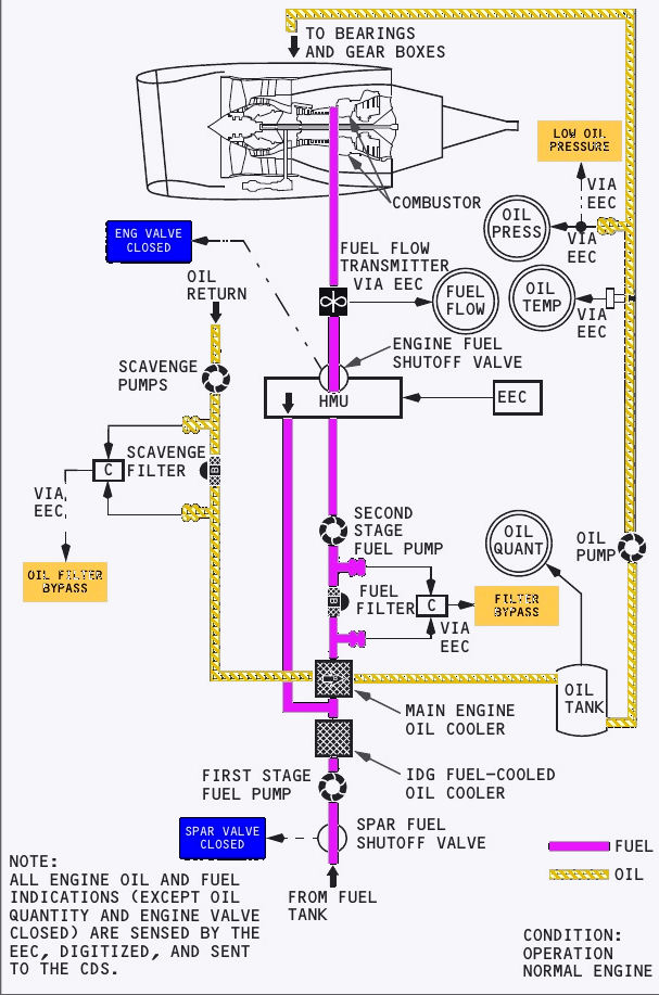
Fuel path and shutoff
Tank pumps deliver fuel to the spar shutoff valve. The first engine-driven pump raises pressure before fuel crosses the IDG and main-engine oil coolers. A filter protects the downstream system, and a second pump raises pressure again before the hydromechanical unit. The EEC commands the HMU to meter the required flow.
Fuel reaches the engine only when both the spar and engine fuel shutoff valves are open. They are commanded open with the fire switch in and the start lever at IDLE. Moving the start lever to CUTOFF or pulling the fire switch commands both valves closed. Fuel flow is sensed after the engine fuel shutoff valve and is sent to both the display system and FMS.
A blocked fuel filter can bypass automatically. FILTER BYPASS illuminates before that bypass occurs, giving the crew warning of the increasing restriction.
Oil pressure, scavenge and cooling
An engine-driven oil pump sends oil to the bearings and accessory gearbox. Pressure and temperature are sensed downstream of the pump before lubrication. Scavenge pumps return oil through a scavenge filter. If that filter approaches bypass, OIL FILTER BYPASS appears before oil takes the bypass path.
Before returning to the tank, oil flows through the main engine oil cooler and gives heat to the fuel. The display presents pressure, temperature, quantity and vibration. For this configuration oil quantity is shown in quarts.
| Indication | Important behaviour |
|---|---|
| Oil pressure | Amber low-pressure band varies above 65 percent N2 and is absent below 65 percent N2 |
| Oil temperature | White normal, amber caution and red operating limit |
| Oil quantity | May fall during start, takeoff and climb, then recover in level flight |
| Windmilling quantity | A value down to zero can be normal below about 8 percent N2 |
Engine start, ignition and protection
The air-driven starter turns N2. Electrical control opens the pneumatic path, and the start lever later introduces fuel and ignition. Ground-start protection can stop fuel and ignition for several abnormal conditions, but it is not available for an in-flight start.
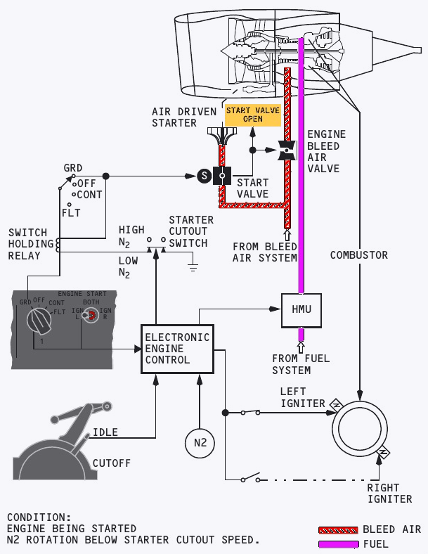
Normal ground-start sequence
The pneumatic source may be the APU, an external air cart or the operating engine. Selecting GRD closes the engine bleed valve and opens the start valve. START VALVE OPEN then confirms air is reaching the starter.
At 25 percent N2 or maximum motoring, the start lever is moved to IDLE. The spar and engine fuel valves open, and the EEC supplies fuel and ignition. EGT can begin to rise before indicated fuel flow because the fuel-flow display lags actual flow by about 2 seconds.
At approximately 56 percent N2, starter cutout releases the start-switch holding circuit. The switch returns to OFF, the start valve closes and the engine bleed valve returns to the selected condition.
Ground-start protection
The EEC watches for an impending hot start, compressor stall, start-limit exceedance and wet start. An approaching hot start or stall first produces a flashing white EGT box. With current EEC software, fuel and ignition are then removed automatically. An actual EGT start-limit exceedance turns the indication red and also commands fuel and ignition off.
A wet start means EGT has not risen after the start lever was placed at IDLE. The EEC removes fuel and ignition 15 seconds after that lever movement. These protections operate only for ground starts.
Igniters and in-flight starts
Each engine has left and right igniter plugs. On this configuration the left igniter normally uses its related AC transfer bus and can transfer to AC standby power if that bus is lost. The right igniter uses the AC standby bus. Automatic relight energises both igniters when the EEC detects a flameout from a rapid uncommanded N2 decrease or an N2 below idle.
In flight, an engine can be started by windmilling or crossbleed. X-BLD appears when airspeed is insufficient for the windmill method. At low N2 the scavenge pumps can produce a temporary low oil quantity indication, which should recover after the start.
Thrust reversers and vibration monitoring
Each engine has two translating reverser sleeves. Hydraulic actuators move the sleeves, blocker doors redirect fan discharge through cascade vanes, and mechanical and hydraulic locks prevent unintended movement.
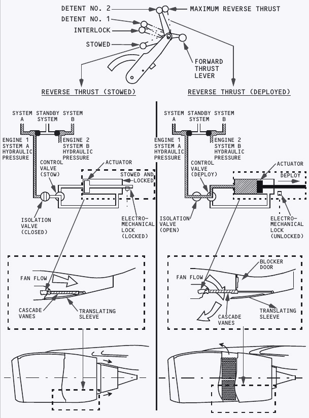
Hydraulic supply and deployment
Hydraulic system A normally operates engine 1 reverse and system B normally operates engine 2 reverse. Standby hydraulics can operate an affected reverser after loss of its normal system, but movement is slower and temporary thrust asymmetry can occur.
Reverse is available for ground operation after touchdown. Deployment logic is satisfied when either radio altimeter senses below 10 feet or the air-ground system indicates ground. The forward thrust lever must be at idle before its reverse lever can be raised.
As a sleeve leaves the stowed position, REV appears amber on the engine display. It becomes green when deployment is complete. An interlock holds the reverse lever near reverse idle until the sleeves have moved far enough, after which detent 2 is available for normal reverse thrust.
Stow protection and indications
Lowering the reverse lever commands the control valve to stow the sleeves. At complete stow, the electro-mechanical lock engages and the isolation valve shuts. Auto-restow compares commanded and actual sleeve positions. If a sleeve drifts toward deployment or fails to stow fully, the circuit reapplies hydraulic pressure in the stow direction.
The overhead REVERSER light normally appears during the stow command and extinguishes about 10 seconds after isolation-valve closure. Illumination for more than approximately 12 seconds indicates a malfunction and brings MASTER CAUTION with the ENG annunciator. Pausing the reverse lever for about 16 seconds beyond reverse-idle detent can engage the lock and stop further sleeve movement.
Airborne vibration monitoring
The vibration system displays synchronous vibration from the low-pressure and high-pressure rotors on the secondary engine display. It also supports balancing of the low-pressure rotor, which can reduce the indication, audible noise and vibration felt through the airframe.
APU architecture, controls and indications
The auxiliary power unit is a self-contained gas turbine in a fire-resistant tail compartment. It can provide pneumatic air and AC electrical power independently of the main engines.
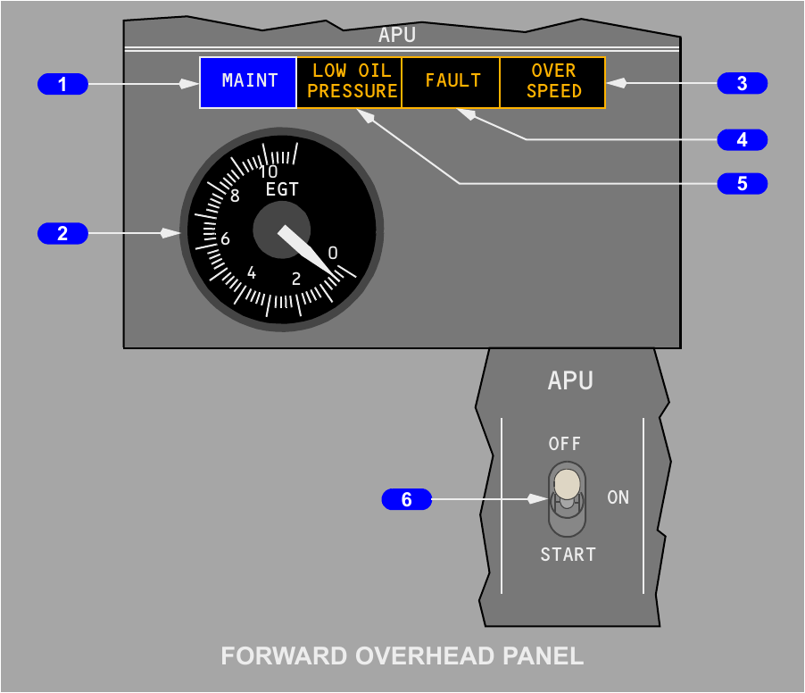
Air, fuel and electrical capability
An automatically controlled inlet door on the right side admits engine air. Separate cooling air enters above the exhaust, circulates through the compartment and oil cooler, then leaves through the exhaust outlet.
On the ground the APU can supply the two air-conditioning packs; in flight its pneumatic capability is limited to one pack. Its generator can power both transfer buses on the ground or in flight. With AC fuel pumps operating, APU fuel comes from the left fuel manifold. Without those pumps, the APU can suction-feed from tank 1. The fuel is heated automatically to resist icing.
Electrical and fire-control prerequisites
The overhead APU fire switch and external ground-control fire handle must both be in. The BAT switch must be ON because removing battery power shuts down the electronic control unit and therefore the APU. The starter-generator uses transfer bus 1 when AC is available and the main battery when it is not.
| Light | Meaning |
|---|---|
| MAINT | A maintenance condition exists, but APU operation remains permitted |
| LOW OIL PRESSURE | Normal during start until pressure rises, or a shutdown cause after start |
| FAULT | A malfunction has caused automatic protective shutdown |
| OVER SPEED | An overspeed shutdown occurred or the protection self-test failed |
The EGT gauge and shutdown lights remain powered for 5 minutes after shutdown. Selecting the APU switch OFF disarms the lights after that interval.
APU start, shutdown and load management
Moving the APU switch momentarily to START begins a fully automatic sequence. The electronic control unit schedules the starter, fuel and ignition, protects the machine and manages the trade between electrical and pneumatic loads.
Automatic start
The inlet door opens first. Once it reaches the required position, the starter accelerates the APU and the controller introduces ignition and fuel. The blue APU GEN OFF BUS light marks the point at which the unit is ready to accept electrical or bleed load.
During a battery-only start, the electrical meters show no APU frequency and zero AC volts until the start is complete. EGT can briefly fluctuate between zero and 1100 degrees C, and LOW OIL PRESSURE can cycle during the sequence. These transients do not require the crew to chase the EGT indication.
The start may take as long as 120 seconds. Failure to reach the required acceleration terminates the attempt automatically, and an EGT exceedance also causes shutdown. If the attempt fails or APU GEN OFF BUS is still absent at the end, FAULT illuminates.
| Timing | Action or meaning |
|---|---|
| 30 seconds minimum | Wait between failed start attempts |
| Three attempts | Maximum consecutive failed attempts before extended cooling |
| 15 minutes | Cooling period after three consecutive failed attempts |
| 2 minutes | Recommended stabilisation before applying bleed-air load |
| 60 seconds | Automatic cooling run after the switch is selected OFF |
Normal and immediate shutdown
Before normal shutdown, remove bleed load and allow one minute without pneumatic extraction. Selecting OFF trips the generator and closes the bleed valve, while an automatic 60-second run satisfies the cooling period. As speed decays, the fuel valve and inlet door close. Pulling the APU fire switch causes an immediate shutdown.
If the fuel valve fails to close, FAULT appears after approximately 30 seconds. The electronic control unit also shuts the APU down for conditions such as overspeed, low oil pressure after the start cycle and other faults that could damage the APU or aircraft.
Load management
If EGT becomes excessive with electrical load only, the controller sheds some electrical demand. During engine start with simultaneous bleed extraction, electrical shedding occurs before bleed is reduced. At other times with both types of load, inlet guide vanes reduce pneumatic extraction while electrical supply is maintained.
When the APU is the sole in-flight AC source, galley and main cabin buses are shed automatically, followed by entertainment buses if demand remains excessive. On the ground the APU first attempts to carry the complete connected demand, then removes galley and main cabin loads as required.